March 2017
Part No. 1268494
S-100 • S-105 • S-120 • S-125
ix
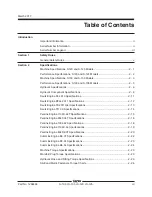
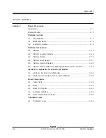
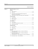
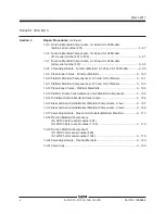
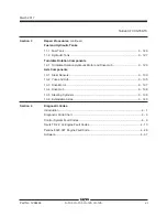
TABLE OF CONTENTS
Section 3
Repair Procedures
, continued
Engines
6-1 RPM Adjustment
.........................................................................................
3 - 56
6-2 Flex Plate
....................................................................................................
3 - 56
6-3 Oil Pressure and Coolant Temperature Sending Units,
Cummins and Perkins Models
.....................................................................
3 - 58
6-4 Oil Pressure and Temperature Sending Units, Deutz Models
.....................
3 - 58
Ground Controls
7-1 Circuit Boards
..............................................................................................
3 - 59
7-2 Membrane Decal
.........................................................................................
3 - 60
7-3 Control Relays
.............................................................................................
3 - 61
Limit Switches
8-1 Limit Switches
.............................................................................................
3 - 64
8-2 Limit Switch and Level Sensor Locations
....................................................
3 - 67
8-3 Limit Switch Functions
.................................................................................
3 - 68
Hydraulic Pumps
9-1 Function Pumps
..........................................................................................
3 - 71
9-2 Drive Pump
..................................................................................................
3 - 72
9-3 Auxiliary Pump
............................................................................................
3 - 75
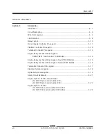
Manifolds
10-1 Function Manifold Components, S-100 and S-105 Models
(serial number 136)
.....................................................................................
3 - 77
10-2 Function Manifold Components, S-100 and S-105 Models
(after serial number 136)
.............................................................................
3 - 81
10-3 Valve Adjustments - Function Manifold, S-100 and S-105 Models
.............
3 - 85
10-4 Proportional Valves - Function Manifold
......................................................
3 - 86
Summary of Contents for S-100
Page 246: ...March 2017 Section 6 Schematics 6 22 Safety Circuit Schematic 6 21 ...
Page 259: ...Section 6 Schematics March 2017 6 35 6 36 Electrical Schematic Generator Options ...
Page 262: ...March 2017 Section 6 Schematics 6 38 6 37 Electrical Schematic 12 kW Generator welder option ...
Page 264: ...March 2017 Section 6 Schematics 6 40 Perkins 1104D 44T Engine Electrical Schematic 6 39 ...
Page 265: ...Section 6 Schematics March 2017 6 41 Perkins 854F 34T Engine Electrical Schematic 6 42 ...
Page 268: ...March 2017 Section 6 Schematics 6 44 Perkins 854F 34T Engine Harness 6 45 ...
Page 269: ...Section 6 Schematics March 2017 6 45 Deutz TD2011L04i Engine Electrical Schematic 6 46 ...
Page 271: ...Section 6 Schematics March 2017 6 47 Deutz TD2 9 Engine Electrical Schematic 6 48 ...
Page 274: ...March 2017 Section 6 Schematics 6 50 Deutz TD2 9 Engine Electrical Harness 6 51 ...
Page 276: ...March 2017 Section 6 Schematics 6 52 6 53 Hydraulic Schematic 12 kW Generator welder option ...


