Part No. 1268494
S-100 • S-105 • S-120 • S-125
3 - 51
March 2017
Section 3 • Repair Procedures
BOOM COMPONENTS
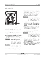
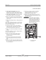
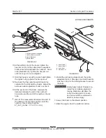
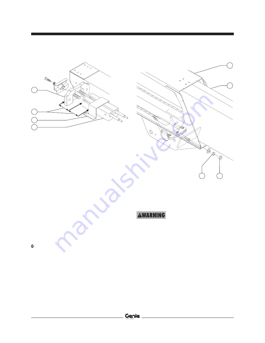
10 At the platform end of the boom, tighten the
hex jam nut (h) on the cable tension equalizer
bracket located underneath the number 1 boom
tube (Illustration 3). Tighten the hex jam nut
until it is snug. Do not overtighten.
11 Hold the hex jam nut with a wrench and tighten
the nylock nut (g) against the hex jam nut.
12 Re-check that the cable break limit switch is
centered in the limit switch actuator. Adjust the
extension cable adjustment bolts to center it.
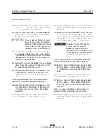
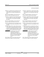
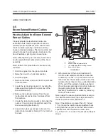
13 At the pivot end of the boom, measure the
distance between the end of the number 3
boom tube and the end of the number 2 boom
tube.
Result: The measurement between the end of
the number 3 boom tube and the end of the
number 2 boom tube should be
6
3
/
4
to
6
7
/
8
inches / 17 to 17.5 cm (d).
e boom tube 1
f boom tube 2
g nylock nut
h hex jam nut
Illustration 3
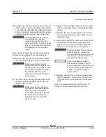
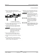
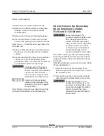
14 Install the red locking bracket over the cable
adjustment bolts. A flat edge of each bolt head (b)
must be on top for the locking bracket to secure
the bolts.
Bodily injury hazard. Failure to re-
install the red cable adjustment
locking bracket would allow the
cable mounting bolts to loosen
and fall out which could result in
death or serious injury.
15 Lower the boom to the stowed position.
16 Start the engine from the platform controls.
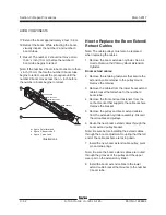
Illustration 2
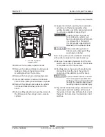
i extension cable coupling
j cable retainer bracket
k equal distance
l guide plate
l
k
j
i
e
g
h
f
Summary of Contents for S-100
Page 246: ...March 2017 Section 6 Schematics 6 22 Safety Circuit Schematic 6 21 ...
Page 259: ...Section 6 Schematics March 2017 6 35 6 36 Electrical Schematic Generator Options ...
Page 262: ...March 2017 Section 6 Schematics 6 38 6 37 Electrical Schematic 12 kW Generator welder option ...
Page 264: ...March 2017 Section 6 Schematics 6 40 Perkins 1104D 44T Engine Electrical Schematic 6 39 ...
Page 265: ...Section 6 Schematics March 2017 6 41 Perkins 854F 34T Engine Electrical Schematic 6 42 ...
Page 268: ...March 2017 Section 6 Schematics 6 44 Perkins 854F 34T Engine Harness 6 45 ...
Page 269: ...Section 6 Schematics March 2017 6 45 Deutz TD2011L04i Engine Electrical Schematic 6 46 ...
Page 271: ...Section 6 Schematics March 2017 6 47 Deutz TD2 9 Engine Electrical Schematic 6 48 ...
Page 274: ...March 2017 Section 6 Schematics 6 50 Deutz TD2 9 Engine Electrical Harness 6 51 ...
Page 276: ...March 2017 Section 6 Schematics 6 52 6 53 Hydraulic Schematic 12 kW Generator welder option ...

