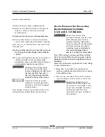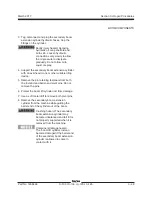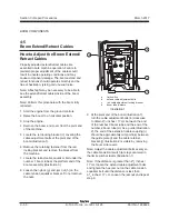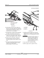
3 - 52
S-100 • S-105 • S-120 • S-125
Part No. 1268494
March 2017
Section 3 • Repair Procedures
BOOM COMPONENTS
How to Replace the Boom Extend/
Retract Cables
Note: The cable pulleys must also be replaced
when replacing the cables.
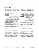
1 Remove the boom extension cylinder. See 4-4,
How to Remove the Primary Boom Extension
Cylinder.
Boom extend cables:
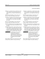
2 Remove the retaining fasteners that secure the
extension cable retainer to the pulley mount.
Remove the retainer.
3 Remove the cables from the lower boom extend
cable bracket that attaches to the number 3
boom tube.
4 Remove the front and rear fasteners from the
anchor bracket that supports the cable anchors.
Remove the bracket.
5 Remove the pulley and boom extend cables
from the extension cylinder assembly. Discard
the old cables and pulleys.
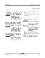
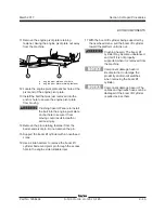
6 Route the new boom extend cables through the
boom extend pulley bracket.
Note: Be sure before installing the extend cables
through the boom adjustment coupling that the tall
end of the cable anchors are facing down.
7 Install the new boom extend cable pulley, pivot
pin and snap rings.
Note: Be sure the boom extend cables are routed
through the grooves of the pulley and the upper
wear pad on the extension cylinder.
8 Install the boom extend cables to the lower
extend cable bracket that mounts to the number
3 boom tube.
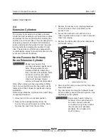
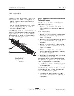
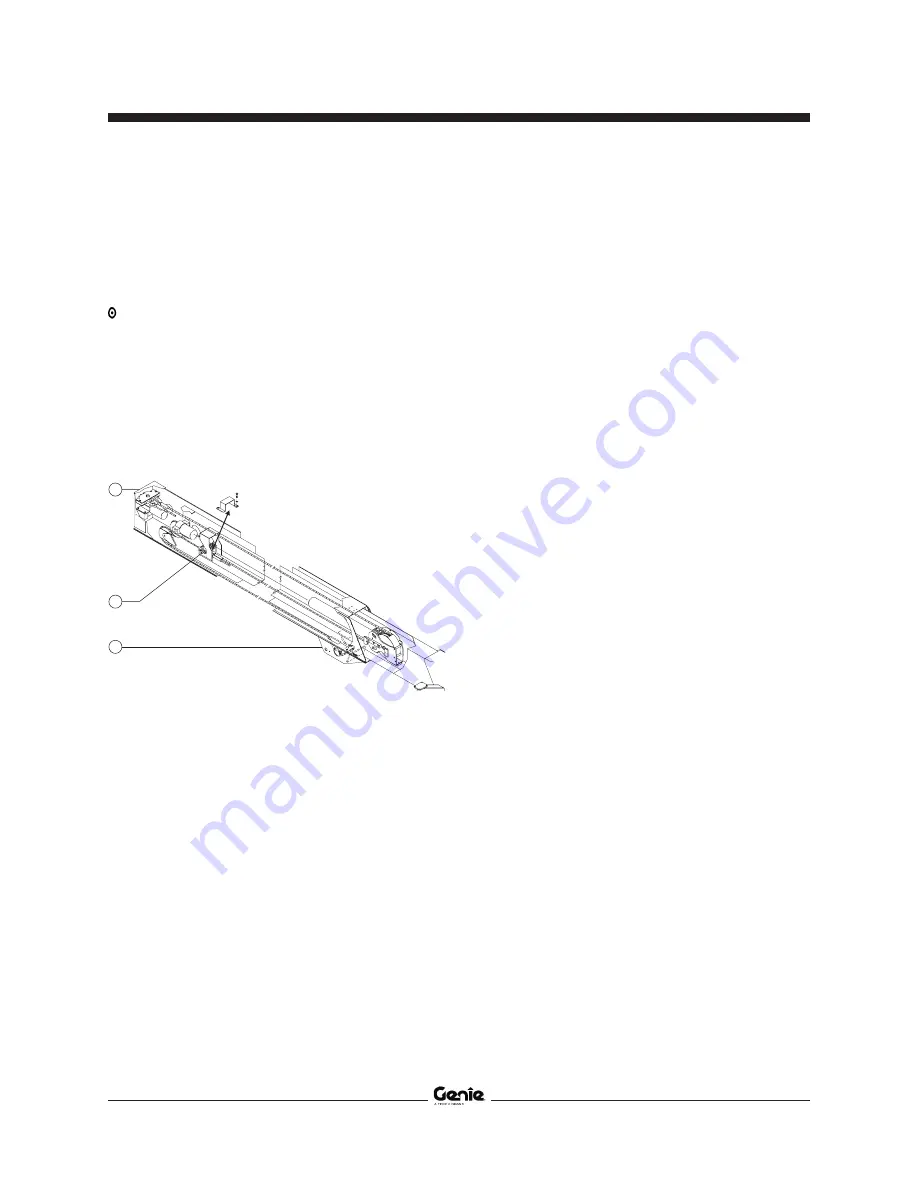
m figure 3 platform end
n figure 2, boom tube 3
o figure 1, pivot end
Illustration 4
Boom Tube One
Boom Tube Two
Boom Tube Three
Boom Tube One
o
n
m
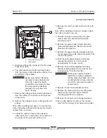
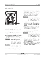
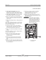
17 Extend the boom approximately 2 feet / 0.6 m.
18 Retract the boom. While retracting the boom,
visually inspect the number 2 and number 3
boom tubes.
Result: The number 2 should not move more
than
1
/
2
inch (13 mm) before the number 3
boom tube begins to retract.
Note: If the number 2 boom tube moves more than
1
/
2
inch (13 mm) before the number 3 boom tube
begins to retract, repeat the procedure until the
number 2 boom moves less than
1
/
2
inch before
the number 3 boom begins to retract
.
Summary of Contents for S-100
Page 246: ...March 2017 Section 6 Schematics 6 22 Safety Circuit Schematic 6 21 ...
Page 259: ...Section 6 Schematics March 2017 6 35 6 36 Electrical Schematic Generator Options ...
Page 262: ...March 2017 Section 6 Schematics 6 38 6 37 Electrical Schematic 12 kW Generator welder option ...
Page 264: ...March 2017 Section 6 Schematics 6 40 Perkins 1104D 44T Engine Electrical Schematic 6 39 ...
Page 265: ...Section 6 Schematics March 2017 6 41 Perkins 854F 34T Engine Electrical Schematic 6 42 ...
Page 268: ...March 2017 Section 6 Schematics 6 44 Perkins 854F 34T Engine Harness 6 45 ...
Page 269: ...Section 6 Schematics March 2017 6 45 Deutz TD2011L04i Engine Electrical Schematic 6 46 ...
Page 271: ...Section 6 Schematics March 2017 6 47 Deutz TD2 9 Engine Electrical Schematic 6 48 ...
Page 274: ...March 2017 Section 6 Schematics 6 50 Deutz TD2 9 Engine Electrical Harness 6 51 ...
Page 276: ...March 2017 Section 6 Schematics 6 52 6 53 Hydraulic Schematic 12 kW Generator welder option ...

