July 2019
Service and Repair Manual
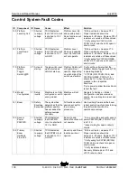
Control System Fault Codes
Part No. 1286829GT
S-
40 XC • S
-
45 XC • S
-
40 TraX •
S-45 TraX
99
ID Component ID Name
Cause
Effect
Solution
94 Primary
Boom Length
13 Not
detected
No CAN messages
have been received
by the TCON from
the Length Sensor.
Boom Up, Extend
and Turntable
Rotate functions will
not operate.
* Verify sensor power P85PWR (GR,
TCON J6-7) is at 12 V while the
system is running.
* Verify the sensor is receiving
power. Unplug the sensor and verify
12 V across pins 1 (+) and 2 (-) on
the harness connector.
* Verify the CAN bus wiring. With the
sensor still unplugged, measure
resistance across harness connector
pins 3 and 4. If resistance is not
between 55 and 65 ohms, check
CAN wire harnesses.
* Replace sensor if necessary.
14 Cross
check
failed
The two internal
sensing channels
inside the Length
Sensor have
registered a
significant
difference.
Machine limited to
recovery functions
* Ensure that the boom angle sensor
cord is hooked up to the bracket on
the boom and that the cord extends
and retracts smoothly.
* Calibrate boom length sensor.
* Replace sensor if necessary.
17 Not
calibrated
Boom length
sensor not
calibrated.
Calibrate boom length sensor.
19 Valut out
of
expected
range
Min or max length
out of expected
range.
* Verify that with the boom retracted
C24LS (OR/RD TCON J7-4) is 12V
and that the boom is making contact
with the LSB1RS limit switch arm.
* Verify that when the boom is
extended at least 10" C24LS
(OR/RD, TCON J7-4) is OV and that
the boom is not making contact with
the LSB1RS limit switch arm.
* Check LSB1RS limit switch for
physical damage.
99 Primary
Boom
Extend /
Retract Flow
Coil
11 Shorted
to supply
voltage
TCON detected
that C9PEF circuit
is shorted to 12 V
or GND.
Boom Extend and
Retract functions
will not operate.
* With a voltmeter, measure Y15.
Proper resistance should be
between 5 - 60 ohms. Replace Y15 if
resistance is outside of those values.
* Verify wiring for C9PEF (BK/RD,
TCON J4-5) and check for open or
short circuits.
* Verify resistance between
Recovery Module pins J37-6 and
J37-7 is zero ohms.
Summary of Contents for S-40 TRAX
Page 144: ...Service and Repair Manual July 2019 134 Electrical Schematic TCON ...
Page 147: ...July 2019 Service and Repair Manual 137 Electrical Schematic PCON ...
Page 148: ...Service and Repair Manual July 2019 138 Electrical Schematic Deutz 2 9 Models ...
Page 150: ...Service and Repair Manual July 2019 140 S 40 XC S 45 XC S 40 TraX S 45 TraX Part No 1286829GT ...
Page 152: ...Service and Repair Manual July 2019 142 Electrical Schematic Deutz 2011 Models ...
Page 153: ...July 2019 Service and Repair Manual 143 Electrical Schematic Perkins 404F Models ...
Page 156: ...Service and Repair Manual July 2019 146 Electrical Schematics Ford MSG425 Models ...
Page 159: ......


