Part No. 147753
S-60 • S-65 • S-60 TRAX • S-65 TRAX
4 - 69
S-60 HC • S-60X • S-60XC
December 2013
Section 4 • Repair Procedures
When installing the drive hub assembly:
6 Install the drive hub. Torque the back lash pivot
plate to specification. Refer to Section 2,
Specifications
.
7 Adjust turntable rotation gear backlash.
See
How to Adjust the Turntable Rotation Gear
Backlash.
How to Adjust the Turntable
Rotation Gear Backlash
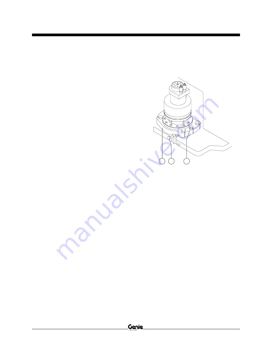
The turntable rotation drive hub is mounted on an
adjustable plate that controls the gap between the
rotation motor pinion gear and the turntable bearing
ring gear.
Note: Perform this procedure with the boom
between the non-steer end tires and with the
machine on a firm and level surface.
1 Secure the turntable from rotating with the
turntable rotation lock pin.
Note: The turntable rotation lock pin is located next
to the boom rest pad.
2 Loosen the backlash pivot plate mounting
fasteners.
a
backlash pivot plate
b
adjustment bolt with lock nut
c
backlash pivot plate mounting bolts
3 Push the backlash pivot plate towards the
turntable as far as possible (this will push the
rotation gear into the turntable bearing ring
gear).
4 Loosen the lock nut on the adjustment bolt.
5 Turn the adjustment bolt clockwise until it
contacts the backlash pivot plate.
6 Turn the adjustment bolt
1
/
2
turn
counterclockwise. Tighten the lock nut on the
adjustment bolt.
7 Rotate the backlash pivot plate away from the
turntable until it contacts the adjustment bolt.
Then torque the mounting fasteners on the
backlash pivot plate to specification. Refer to
Section 2,
Specifications
.
8 Rotate the turntable through an entire rotation.
Check for tight spots that could cause binding.
Readjust if necessary.
a
b
c
TURNTABLE ROTATION COMPONENTS
Summary of Contents for S-60 HC
Page 1: ......
Page 215: ...Section 6 Schematics December2013 6 7 Ford DSG 423 Engine Wire Harness 6 8 ...
Page 218: ...December2013 Section 6 Schematics 6 10 Ford MSG 425 Engine Wire Harness 6 9 ...
Page 219: ...Section 6 Schematics December2013 6 11 Electrical Schematic Options All Models 6 12 ...
Page 222: ...December2013 Section 6 Schematics 6 14 Wiring Diagram Belt Driven Generator 6 13 ...
Page 223: ...Section 6 Schematics December2013 6 15 Wiring Diagram 3kW Hydraulic Generator 6 16 ...
Page 234: ...December2013 Section 6 Schematics 6 26 Hydraulic Schematic 2WD Models after SN 21396 6 25 ...
Page 238: ...December2013 Section 6 Schematics 6 30 Hydraulic Schematic 4WD Models after SN 21396 6 29 ...
Page 365: ...Section 6 Schematics December2013 6 157 Electrical Schematic S 60 HC CE 6 158 ...
Page 368: ...December2013 Section 6 Schematics 6 160 Chassis Wiring Diagram S 60 HC CE 6 159 ...
Page 373: ...Section 6 Schematics December2013 6 165 Platform Control Box Wiring Diagram S 60 HC CE 6 166 ...
Page 461: ......


