September 2015
Service and Repair Manual
Primary Boom Components
Part No. 1268515
Z-34/22 Bi-Energy
25
Primary Boom Components
4-1 C able Track
4-1
Cable Track
The primary boom cable track guides the cables
and hoses running up the boom. It can be repaired
link by link without removing the cables and hoses
that run through it. Removing the entire primary
boom cable track is only necessary when
performing major repairs that involve removing the
primary boom.
How to R epair the Primary Boom C abl e Tr ack
How to Repair the Primary Boom
Cable Track
Component damage hazard.
The boom cable track can be
damaged if it is twisted.
Note: A 7 link repair section of cable track is
available through the Genie Service Parts
Department.
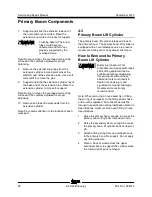
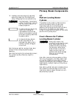
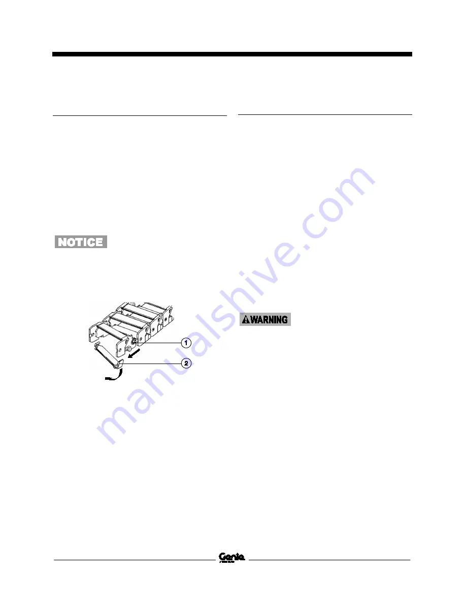
1 link separation point
2 lower clip
1 Use a slotted screwdriver to pry down on the
lower clip.
2 To remove a single link, open the lower clip
and then use a screw driver to pry the link to
the side.
3 Repeat steps 1 and 2 for each link.
4-2 Primary Boom
4-2
Primary Boom
How to Shim the Primary Boom
How to Shim the Primary Boom
1 Extend the boom until the wear pads are
accessible.
2 Loosen the wear pad mounting fasteners.
3 Install the new shims under the wear pad to
obtain zero clearance and zero drag.
4 Tighten the mounting fasteners.
5 Extend and retract the boom through an entire
cycle. Check for tight spots that could cause
scraping or binding.
Note: Always maintain squareness between the
outer and inner boom tubes.
How to R emove the Primary Boom
How to Remove the Primary
Boom
Bodily injury hazard. This
procedure requires specific repair
skills, lifting equipment and a
suitable workshop. Attempting
this procedure without these
skills and tools could result in
death or serious injury and
significant component damage.
Dealer service is strongly
recommended.
Note: When removing a hose assembly or fitting,
the O-ring (if equipped) on the fitting and/or hose
end must be replaced. All connections must be
torqued to specification during installation. Refer to
Specifications,
Hydraulic Hose and Fitting Torque
Specifications.
Note: Perform this procedure with the boom in the
stowed position.
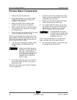
1 Remove the platform.
Summary of Contents for Z-22 Bi-Energy
Page 63: ...September 2015 Service and Repair Manual Manifolds Part No 1268515 Z 34 22 Bi Energy 51...
Page 99: ...September 2015 Service and Repair Manual 87 Electrical Schematic from serial number 5427 CE...
Page 102: ...Service and Repair Manual September 2015 90 Electrical Schematic from serial number 5427 CE...
Page 103: ...September 2015 Service and Repair Manual 91 Ground Control Box Switch Panel Wiring Diagram...
Page 106: ...Service and Repair Manual September 2015 94 Ground Control Box Terminal Strip Wiring Diagram...
Page 107: ...September 2015 Service and Repair Manual 95 Platform Control Box Wiring Diagram...
Page 110: ...Service and Repair Manual September 2015 98 Power Cable Wiring Diagram...
Page 111: ...September 2015 Service and Repair Manual 99 Drive Contactor Panel Wiring Diagram...
Page 114: ...Service and Repair Manual September 2015 102 Manifold and Limit Switch Wiring Diagram...
Page 119: ...September 2015 Service and Repair Manual 107 Engine Wiring Diagram...
Page 123: ......

