Service and Repair Manual
September 2015
Specifications
8
Z-34/22 Bi-Energy
Part No. 1268515
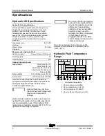
Hydraulic H ose and Fitting T orque Specifications
Hydraulic Hose and Fitting
Torque Specifications
Your machine is equipped with Parker Seal-Lok™
ORFS or 37° JIC fittings and hose ends. Genie
specifications require that fittings and hose ends
be torqued to specification when they are removed
and installed or when new hoses or fittings are
installed.
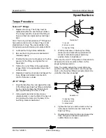
Seal-Lok™ Fittings
(hose end - ORFS)
SAE Dash Size
Torque
-4
10 ft-lbs / 13.6 Nm
-6
30 ft-lbs / 40.7 Nm
-8
40 ft-lbs / 54.2 Nm
-10
60 ft-lbs / 81.3 Nm
-12
85 ft-lbs / 115 Nm
-16
110 ft-lbs / 150 Nm
-20
140 ft-lbs / 190 Nm
-24
180 ft-lbs / 245 Nm
JIC 37° Fittings
(swivel nut or hose connection)
SAE Dash Size
Thread Size
Flats
-4
7/16-20
2
-6
9/16-18
1 ¼
-8
3/4-16
1
-10
7/8-14
1
-12
1 1/16-12
1
-16
1 5/16-12
1
-20
1 5/8-12
1
-24
1 7/8-12
1
SAE O-ring Boss Port
(tube fitting - installed into Aluminum)
(all types)
SAE Dash Size
Torque
-4
14 ft-lbs / 19 Nm
-6
23 ft-lbs / 31.2 Nm
-8
36 ft-lbs / 54.2 Nm
-10
62 ft-lbs / 84 Nm
-12
84 ft-lbs / 114 Nm
-16
125 ft-lbs / 169.5 Nm
-20
151 ft-lbs / 204.7 Nm
-24
184 ft-lbs / 249.5 Nm
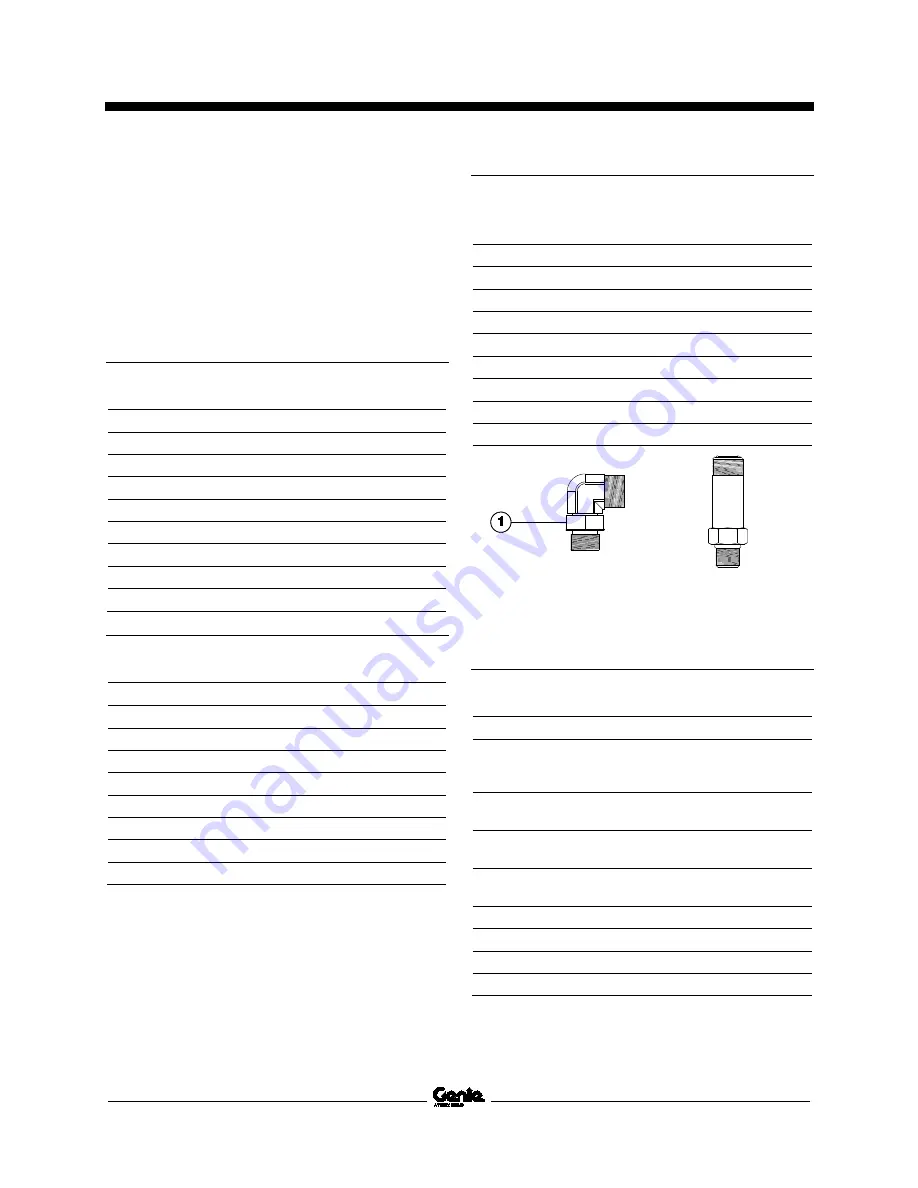
Adjustable Fitting
Non-adjustable fitting
1 jam nut
SAE O-ring Boss Port
(tube fitting - installed into Steel)
SAE Dash Size
Torque
-4
ORFS / 37° (Adj)
ORFS (Non-adj)
37° (Non-adj)
15 ft-lbs / 20.3 Nm
26 ft-lbs / 35.3 Nm
22 ft-lbs / 30 Nm
-6
ORFS (Adj / Non-adj)
37° (Adj / Non-adj)
35 ft-lbs / 47.5 Nm
29 ft-lbs / 39.3 Nm
-8
ORFS (Adj / Non-adj)
37° (Adj / Non-adj)
60 ft-lbs / 81.3 Nm
52 ft-lbs / 70.5 Nm
-10 ORFS (Adj / Non-adj)
37° (Adj / Non-adj)
100 ft-lbs / 135.6 Nm
85 ft-lbs / 115.3 Nm
-12 (All types)
135 ft-lbs / 183 Nm
-16 (All types)
200 ft-lbs / 271.2 Nm
-20 (All types)
250 ft-lbs / 339 Nm
-24 (All types)
305 ft-lbs / 413.5 Nm
Summary of Contents for Z-22 Bi-Energy
Page 63: ...September 2015 Service and Repair Manual Manifolds Part No 1268515 Z 34 22 Bi Energy 51...
Page 99: ...September 2015 Service and Repair Manual 87 Electrical Schematic from serial number 5427 CE...
Page 102: ...Service and Repair Manual September 2015 90 Electrical Schematic from serial number 5427 CE...
Page 103: ...September 2015 Service and Repair Manual 91 Ground Control Box Switch Panel Wiring Diagram...
Page 106: ...Service and Repair Manual September 2015 94 Ground Control Box Terminal Strip Wiring Diagram...
Page 107: ...September 2015 Service and Repair Manual 95 Platform Control Box Wiring Diagram...
Page 110: ...Service and Repair Manual September 2015 98 Power Cable Wiring Diagram...
Page 111: ...September 2015 Service and Repair Manual 99 Drive Contactor Panel Wiring Diagram...
Page 114: ...Service and Repair Manual September 2015 102 Manifold and Limit Switch Wiring Diagram...
Page 119: ...September 2015 Service and Repair Manual 107 Engine Wiring Diagram...
Page 123: ......

