September 2015
Service and Repair Manual
Specifications
Part No. 1268515
Z-34/22 Bi-Energy
9
Torque Pr ocedure
Torque Procedure
Seal-Lok™ fittings
1 Replace the O-ring. The O-ring must be
replaced anytime the seal has been broken.
The O-ring cannot be re-used if the fitting or
hose end has been tightened beyond finger
tight.
Note: The O-ring in Parker Seal Lok™ fittings and
hose end are custom-size O-rings. They are not
standard size O-rings. They are available in the
O-ring field service kit (Genie part number 49612).
2 Lubricate the O-ring before installation.
3 Be sure the O-ring face seal is seated and
retained properly.
4 Position the tube and nut squarely on the face
seal end of the fitting, and tighten the nut
finger tight.
5 Tighten the nut or fitting to the appropriate
torque. Refer to the appropriate torque chart
in this section.
6 Operate all machine functions and inspect the
hose, fittings and related components to
confirm there are no leaks.
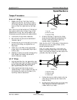
JIC 37° fittings
1 Align the tube flare (hex nut) against the nose
of the fitting body (body hex fitting) and tighten
the hex nut to the body hex fitting to hand
tight, approximately 30 in-lbs / 3.4 Nm.
2 Using a permanent ink marker, make a
reference mark on one the flats of the hex nut
and continue the mark onto the body of the
hex fitting. Refer to Illustration 1.
Illustration 1
1 hex nut
2 reference mark
3 body hex fitting
3 Working clockwise on the body hex fitting,
make a second mark with a permanent ink
marker to indicate the proper tightening
position. Refer to Illustration 2.
Note: Use the JIC 37° Fitting table in this section to
determine the correct number of flats, for the
proper tightening position.
Note: The marks indicate the correct tightening
positions have been determined. Use the second
mark on the body hex fitting to properly tighten the
joint after it has been loosened.
Illustration 2
1 body hex fitting
2 reference mark
3 second mark
4 Tighten the hex nut until the mark on the hex
nut is aligned with the second mark on the
body hex fitting.
5 Operate all machine functions and inspect the
hose, fittings and related components to
confirm there are no leaks.
Summary of Contents for Z-22 Bi-Energy
Page 63: ...September 2015 Service and Repair Manual Manifolds Part No 1268515 Z 34 22 Bi Energy 51...
Page 99: ...September 2015 Service and Repair Manual 87 Electrical Schematic from serial number 5427 CE...
Page 102: ...Service and Repair Manual September 2015 90 Electrical Schematic from serial number 5427 CE...
Page 103: ...September 2015 Service and Repair Manual 91 Ground Control Box Switch Panel Wiring Diagram...
Page 106: ...Service and Repair Manual September 2015 94 Ground Control Box Terminal Strip Wiring Diagram...
Page 107: ...September 2015 Service and Repair Manual 95 Platform Control Box Wiring Diagram...
Page 110: ...Service and Repair Manual September 2015 98 Power Cable Wiring Diagram...
Page 111: ...September 2015 Service and Repair Manual 99 Drive Contactor Panel Wiring Diagram...
Page 114: ...Service and Repair Manual September 2015 102 Manifold and Limit Switch Wiring Diagram...
Page 119: ...September 2015 Service and Repair Manual 107 Engine Wiring Diagram...
Page 123: ......

