Z-30/20N • Z-30/20N RJ • Z-34/22 • Z-34/22N
Part No. 139378
June 2011
x
Section 4
Rev
Repair Procedures,
continued
A
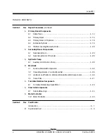
Primary Boom Components
4-1
Cable Track ................................................................................................ 4 - 14
4-2
Primary Boom ............................................................................................ 4 - 14
4-3
Primary Boom Lift Cylinder ......................................................................... 4 - 18
4-4
Extension Cylinder ..................................................................................... 4 - 19
4-5
Platform Leveling Master Cylinder .............................................................. 4 - 20
A
Secondary Boom Components
5-1
Secondary Boom ........................................................................................ 4 - 23
5-2
Secondary Boom Lift Cylinder .................................................................... 4 - 28
A
Hydraulic Pump
6-1
Auxiliary and Function Pump ...................................................................... 4 - 30
B
Manifolds
7-1
Function Manifold Components .................................................................. 4 - 32
7-2
Valve Adjustments - Function Manifold ...................................................... 4 - 36
7-3
Jib Boom and Platform / Jib Boom Rotate Manifold Components ............... 4 - 39
7-4
Valve Coils ................................................................................................. 4 - 41
A
Turntable Rotation Components
8-1
Turntable Rotation Hydraulic Motor ............................................................. 4 - 43
A
Steer Axle Components
9-1
Hub and Bearings ....................................................................................... 4 - 44
A
Motor Controller
10-1 Motor Controller .......................................................................................... 4 - 45
Section 5
Rev
Fault Codes
Introduction ............................................................................................................ 5 - 1
B
Fault Code Chart .................................................................................................... 5 - 3
TABLE OF CONTENTS
Summary of Contents for Z-30/20N
Page 1: ......
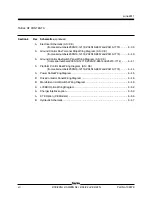
Page 148: ...6 46 June2011 Section 6 Schematics 6 45 Power Cable Wiring Diagram...
Page 149: ...6 47 Section 6 Schematics June2011 6 48 Drive Contactor Panel Wiring Diagram...
Page 152: ...6 50 June2011 Section 6 Schematics Manifold and Limit Switch Wiring Diagram 6 49...
Page 153: ...6 51 Section 6 Schematics June2011 6 52 LVI BCI Option Wiring Diagram...
Page 156: ...6 54 June2011 Section 6 Schematics 6 53 Charger Interlock Option...
Page 157: ...6 55 Section 6 Schematics June2011 6 56 CTE Option CE Models...
Page 160: ...6 58 June2011 Section 6 Schematics Hydraulic Schematic 6 57...


