4 - 2
Z-30/20N • Z-30/20N RJ • Z-34/22 • Z-34/22N
Part No. 139378
June 2011
Section 4 • Repair Procedures
REV A
1-1
Controllers
The drive joystick is connected to the drive motor
controller, located under the drive chassis cover at
the non-steer end of the machine. Maintaining the
boom function speed controller at the proper
settings is essential to safe machine operation.
The boom function speed controller should operate
smoothly and provide proportional speed control
through its entire range of motion. For further
information or assistance, contact the Genie
Industries Service Department.
a
boom function speed controller
b
drive and brake printed circuit board
c
drive joystick
Boom Function Speed
Controller Adjustments
Electrocution/burn hazard. Contact
with electrically charged circuits
could result in death or serious
injury. Remove all rings, watches
and other jewelry.
Note: Do not adjust the boom function speed
controller unless the static battery supply voltage is
above 24V DC.
1 Turn the key switch to platform controls and pull
out the red Emergency Stop button to the on
position at both the ground and platform
controls.
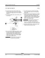
2 Open the platform control box lid and locate the
boom function speed controller.
a
black/red wire
b
diode
c
white/red wire
d
boom function speed controller
e
ramp rate trimpot
f
threshold trimpot
g
max out trimpot
Platform Controls
a
b
c
a
b
c
d
f
g
e
Summary of Contents for Z-30/20N
Page 1: ......
Page 148: ...6 46 June2011 Section 6 Schematics 6 45 Power Cable Wiring Diagram...
Page 149: ...6 47 Section 6 Schematics June2011 6 48 Drive Contactor Panel Wiring Diagram...
Page 152: ...6 50 June2011 Section 6 Schematics Manifold and Limit Switch Wiring Diagram 6 49...
Page 153: ...6 51 Section 6 Schematics June2011 6 52 LVI BCI Option Wiring Diagram...
Page 156: ...6 54 June2011 Section 6 Schematics 6 53 Charger Interlock Option...
Page 157: ...6 55 Section 6 Schematics June2011 6 56 CTE Option CE Models...
Page 160: ...6 58 June2011 Section 6 Schematics Hydraulic Schematic 6 57...


