4 - 6
Z-30/20N • Z-30/20N RJ • Z-34/22 • Z-34/22N
Part No. 139378
June 2011
Section 4 • Repair Procedures
REV A
PLATFORM COMPONENTS
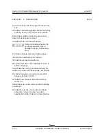
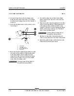
2 Connect a clear hose to the top bleed valve.
Place the other end of the hose in a container
to collect any drainage. Secure the container to
the boom.
3 Open the top bleed valve on the rotator, but do
not remove it.
a
clear hose
b
top bleed valve
c
bottom bleed valve
d
container
4 Move the function enable toggle switch to either
side and hold the platform rotate toggle switch
to the left position until the platform is fully
rotated to the left. Continue holding the toggle
switch until air stops coming out of the bleed
valve. Close the bleed valve.
Crushing hazard. Keep clear of
the platform during rotation.
5 Connect the clear hose to the bottom bleed
valve and open the valve. Do not remove the
bleed valve.
6 Move the function enable toggle switch to either
side and hold the platform rotate toggle switch
to the right position until the platform is fully
rotated to the right. Continue holding the toggle
switch until air stops coming out of the bleed
valve. Close the bleed valve.
Crushing hazard. Keep clear of
the platform during rotation.
7 Remove the hose from the bleed valve and
clean up any hydraulic oil that may have spilled.
8 Rotate the platform fully in both directions and
inspect the bleed valves for leaks.
b
c
d
a
Summary of Contents for Z-30/20N
Page 1: ......
Page 148: ...6 46 June2011 Section 6 Schematics 6 45 Power Cable Wiring Diagram...
Page 149: ...6 47 Section 6 Schematics June2011 6 48 Drive Contactor Panel Wiring Diagram...
Page 152: ...6 50 June2011 Section 6 Schematics Manifold and Limit Switch Wiring Diagram 6 49...
Page 153: ...6 51 Section 6 Schematics June2011 6 52 LVI BCI Option Wiring Diagram...
Page 156: ...6 54 June2011 Section 6 Schematics 6 53 Charger Interlock Option...
Page 157: ...6 55 Section 6 Schematics June2011 6 56 CTE Option CE Models...
Page 160: ...6 58 June2011 Section 6 Schematics Hydraulic Schematic 6 57...


