Part No. 139378
Z-30/20N • Z-30/20N RJ • Z-34/22 • Z-34/22N
4 - 13
June 2011
Section 4 • Repair Procedures
REV A
3-4
Jib Boom Lift Cylinder
How to Remove the Jib Boom
Lift Cylinder
Note: When removing a hose assembly or
fitting, the O-ring on the fitting and/or hose end
must be replaced and then torqued to
specification during installation. Refer to
Section 2,
Hydraulic Hose and Fitting Torque
Specifications.
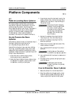
1 Raise the jib boom slightly and place blocks
under the platform mounting weldment for
support. Lower the jib boom until the platform is
resting on the blocks.
2 Tag, disconnect and plug the jib boom lift
cylinder hydraulic hoses. Cap the fittings on the
cylinder.
Bodily injury hazard. Spraying
hydraulic oil can penetrate and
burn skin. Loosen hydraulic
connections very slowly to allow
the oil pressure to dissipate
gradually. Do not allow oil to
squirt or spray.
3 Remove the pin retaining fasteners from the jib
boom lift cylinder rod-end pivot pin. Do not
remove the pin.
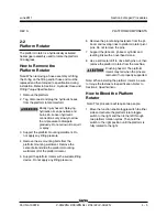
4 Use a soft metal drift to tap the rod-end pivot
pin half way out and lower one of the leveling
links to the ground. Tap the pin the other
direction and lower the opposite leveling link.
Do not remove the pin.
5 Attach a lifting strap from an overhead crane to
the rod end of the jib boom lift cylinder.
6 Remove the pin retaining fasteners from the jib
boom lift cylinder barrel-end pivot pin. Use a
soft metal drift to remove the barrel-end pivot
pin.
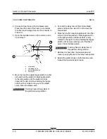
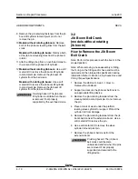
7 Use a soft metal drift to remove the jib boom lift
cylinder rod-end pivot pin. Remove the jib boom
lift cylinder from the machine.
Crushing hazard. The jib boom lift
cylinder could fall when the pins
are removed if not properly
supported by the overhead crane.
JIB BOOM COMPONENTS
Summary of Contents for Z-30/20N
Page 1: ......
Page 148: ...6 46 June2011 Section 6 Schematics 6 45 Power Cable Wiring Diagram...
Page 149: ...6 47 Section 6 Schematics June2011 6 48 Drive Contactor Panel Wiring Diagram...
Page 152: ...6 50 June2011 Section 6 Schematics Manifold and Limit Switch Wiring Diagram 6 49...
Page 153: ...6 51 Section 6 Schematics June2011 6 52 LVI BCI Option Wiring Diagram...
Page 156: ...6 54 June2011 Section 6 Schematics 6 53 Charger Interlock Option...
Page 157: ...6 55 Section 6 Schematics June2011 6 56 CTE Option CE Models...
Page 160: ...6 58 June2011 Section 6 Schematics Hydraulic Schematic 6 57...

