Part No. 29487
Genie Z-45/22
7 - 23
Service Manual - First Edition
Section 7 - Repair Procedures
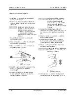
The upper mid-pivot rest should
be approximately 1 inch (2.5cm)
above the rest block.
The upper mid-pivot rest should
be approximately 4 inches
(10cm) above the rest block.
11 Lift the number 1 arm until the secondary lift
cylinders can swing forward to rest on the
lower mid-pivot.
12 Remove the block between the counterweight
and the upper mid-pivot.
13 Lower the arms enough to relieve the pressure
on the compression link upper pivot pin.
Specification: to remove pressure on the
compression link
Industrial tires
Rough terrain tires
14 Remove the pin retaining fastener from the
compression link to number 1 arm pivot pin.
Use a soft metal drift to remove the pin.
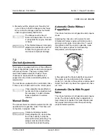
15 Lower the arms to full rest and re-position the
lifting strap to the center of the number 1 arm.
16 Remove the pin retaining fastener from the
lower mid-pivot to number 1 arm pivot pin. Use
a soft metal drift to remove the pin.
17 Remove the pin retaining fastener from the
upper mid-pivot to number 1 arm pivot pin. Use
a slide hammer to remove the pin.
Crushing hazard. If the overhead
crane is not properly attached, the
number 1 arm may become
unbalanced and fall when it is
disconnected from the upper
mid-pivot.
18 Carefully remove the number 1 arm from the
machine.
19 Number each electrical cable and its entry
location at the platform control box.
20 Open the platform control box and label each
wire termination from the cables. Disconnect all
control cable wiring from the platform control
box.
21 Pull all of the electrical cables out of the plastic
cable track. Do not pull out the hydraulic
cables.
22 Disconnect and plug the platform rotator
hydraulic hoses at the union, located near the
upper mid-pivot. Remove the cable track
assembly from the machine.
Bodily injury hazard. Spraying
hydraulic oil can perforate and
burn skin. Loosen hydraulic
connections very slowly to allow
the oil pressure to dissipate
gradually. Do not allow oil to squirt
or spray.
23 Remove the upper and lower cable trays from
the number 2 arm. Also remove the upper
cable tray from the number 3 arm.
24 Pull all of the cables and hoses down through
the upper mid-pivot.
Component damage hazard.
Cables and hoses can be
irreparably damaged if they are
kinked or pinched.
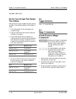
25 Attach a lifting strap from an overhead crane to
the upper mid-pivot. Then place a hydraulic
jack between arm numbers 2 and 3 at the end
nearest the upper mid-pivot end of the arms.
26 Adjust the hydraulic jack and overhead crane to
relieve the pressure on the pivot pin connecting
the number 2 arm to the upper mid-pivot.
27 Remove the pin retaining fastener from the
upper mid-pivot to number 2 arm pivot pin. Use
a slide hammer to remove the pin.
Crushing hazard. The upper
mid-pivot will fall if it is not
properly supported when the pivot
pin is removed.
SECONDARY BOOM COMPONENTS
Summary of Contents for Z-45/22
Page 1: ...Technical Publications First Edition Part No 29487 Service Manual Z 45 22 ...
Page 121: ...6 3 ...
Page 122: ......
Page 123: ...6 5 ...
Page 124: ...6 6 ...
Page 125: ...6 7 ...
Page 126: ...6 8 ...
Page 127: ......
Page 128: ...6 10 ...
Page 129: ...6 11 ...
Page 130: ...6 12 ...
Page 132: ...Z45 22 Hyd Index ...
Page 133: ...Z45 22 Hyd Index ...
Page 134: ...Z45 22 Hyd Index ...
Page 135: ...Z45 22 Hyd Index ...
Page 136: ...Z45 22 Hyd Index ...
Page 137: ...Z45 22 Hyd Index ...


