4 - 32
Genie Z-60/34
Part No. 75861
November 2003
Section 4 • Repair Procedures
REV A
6-1
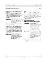
RPM Adjustment - Ford and
Deutz Models
Refer to Maintenance Procedure B-10, Check and
Adjust the Engine RPM- Ford and Deutz Models.
6-2
Flex Plate
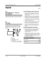
The flex plate acts as a coupler between the
engine and the pump. It is bolted to the engine
flywheel and has a splined center to drive the
pump.
a
pump
b
pump shaft
c
pump coupler
d
flex plate with raised spline
e
engine flywheel
f
3
/
8
inch / 9.5 mm gap - Deutz Models
1
/
16
inch / 1.6 mm gap - Ford Models
How to Remove the Flex Plate
1 Disconnect the wiring plug at the electronic
displacement controller (EDC), located on
the drive pump.
2 Support the drive pump with an appropriate
lifting device. Then remove all of the pump
mounting plate to engine bell housing bolts.
3 Carefully pull the pump away from the engine
and secure it from moving.
4 Remove the medium pressure filter and high
pressure filter (if equipped) and bracket.
5 Remove the flex plate mounting fasteners,
then remove the flex plate from the engine
flywheel.
How to Install the Flex Plate
1 Install the flex plate onto the engine flywheel
with the raised spline towards the pump.
Torque the flex plate mounting bolts to
34 ft-lbs / 46 Nm.
2 Install the pump coupler onto the pump shaft
with the set screw toward the pump. Leave the
appropriate gap between coupler and pump
end plate for your engine.
Pump coupler gap specification
Deutz models
3
/
8
inch
9.5 mm
Ford models
1
/
16
inch
1.6 mm
Engines
a
b
c
d
e
f
Summary of Contents for Z-60/34
Page 12: ...Genie Z 60 34 Part No 75861 November 2003 This page intentionally left blank ...
Page 157: ......
Page 160: ...Electrical Schematic Deutz F4L 1011F Models November 2003 Section 6 Schematics ...
Page 162: ...Ground Control Box Wiring Diagram Deutz F4L 1011F Models November 2003 Section 6 Schematics ...
Page 164: ...Platform Control Box Wiring Diagram Deutz F4L 1011F Models November 2003 Section 6 Schematics ...
Page 165: ......
Page 168: ...Electrical Schematic Ford LRG 425 EFI Models November 2003 Section 6 Schematics ...
Page 170: ...Ground Control Box Wiring Diagram Ford LRG 425 EFI Models November 2003 Section 6 Schematics ...
Page 173: ...November2003 Section 6 Schematics PartNo 75861 GenieZ 60 34 6 11 ...
Page 176: ...Hydraulic Schematic 2WD Models before serial number 4461 November 2003 Section 6 Schematics ...
Page 178: ...Hydraulic Schematic 4WD Models before serial number 4461 November 2003 Section 6 Schematics ...
Page 180: ...Hydraulic Schematic 2WD Models after serial number 4460 November 2003 Section 6 Schematics ...
Page 182: ...Hydraulic Schematic 4WD Models after serial number 4460 November 2003 Section 6 Schematics ...


