Part No. 75861
Genie Z-60/34
4 - 57
November 2003
Section 4 • Repair Procedures
REV A
8-12
Valve Adjustments, 4WD
Drive Manifold
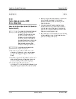
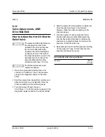
How to Adjust the Hot Oil Shuttle
Relief Valve
The pressure differential between
the charge pump relief valve
(located in the drive pump) and
the hot oil shuttle relief valve
(located in the drive manifold) is
necessary to return hot oil from
the closed loop drive circuit to the
hydraulic tank for cooling. This
pressure differential must be
maintained at 40 psi / 14.5 bar.
The following procedure will
require two people.
1 Open the engine side turntable cover and
connect a 0 to 600 psi / 0 to 41 bar pressure
gauge to the diagnostic nipple on the drive
pump.
2 Start the engine from the platform controls and
allow the engine to run at high idle. Note the
pressure reading on the pressure gauge.
3 Turn the engine off and connect a
0 to 600 psi / 0 to 41 bar pressure gauge to the
diagnostic nipple located on the drive manifold.
4 Start the engine from the platform controls and
drive the machine slowly in the forward
direction. Note the pressure reading on the
pressure gauge.
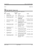
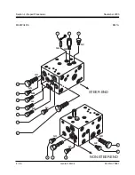
5 Turn the engine off, and remove the hot oil
shuttle relief valve cap (item BB). Adjust the
internal hex socket clockwise to increase the
pressure or counterclockwise to decrease the
pressure. Install the valve cap.
6 Repeat steps 4 and 5 until the pressure reading
on the guage is 40 psi / 2.8 bar less than the
pressure reading at the pump.
Hot oil shuttle relief valve specification
Pressure
280 psi
19.3 bar
MANIFOLDS
Summary of Contents for Z-60/34
Page 12: ...Genie Z 60 34 Part No 75861 November 2003 This page intentionally left blank ...
Page 157: ......
Page 160: ...Electrical Schematic Deutz F4L 1011F Models November 2003 Section 6 Schematics ...
Page 162: ...Ground Control Box Wiring Diagram Deutz F4L 1011F Models November 2003 Section 6 Schematics ...
Page 164: ...Platform Control Box Wiring Diagram Deutz F4L 1011F Models November 2003 Section 6 Schematics ...
Page 165: ......
Page 168: ...Electrical Schematic Ford LRG 425 EFI Models November 2003 Section 6 Schematics ...
Page 170: ...Ground Control Box Wiring Diagram Ford LRG 425 EFI Models November 2003 Section 6 Schematics ...
Page 173: ...November2003 Section 6 Schematics PartNo 75861 GenieZ 60 34 6 11 ...
Page 176: ...Hydraulic Schematic 2WD Models before serial number 4461 November 2003 Section 6 Schematics ...
Page 178: ...Hydraulic Schematic 4WD Models before serial number 4461 November 2003 Section 6 Schematics ...
Page 180: ...Hydraulic Schematic 2WD Models after serial number 4460 November 2003 Section 6 Schematics ...
Page 182: ...Hydraulic Schematic 4WD Models after serial number 4460 November 2003 Section 6 Schematics ...

