3 - 12
Genie Z-60/34
Part No. 75861
November 2003
Section 3 • Scheduled Maintenance Procedures
REV A
CHECKLIST
A
PROCEDURES
A-11
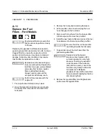
Replace the Fuel
Filters - Ford Models
Engine specifications require that
this procedure be performed every
100 hours.
Replacing the gasoline fuel filters is essential to
good engine performance and service life. A dirty or
clogged filter may cause the engine to perform
poorly and continued use may cause component
damage. Extremely dirty conditions may require
that the filter be replaced more often.
Explosion and fire hazard. Engine
fuels are combustible. Replace the
fuel filter in an open, well-ventilated
area away from heaters, sparks,
flames and lighted tobacco.
Always have an approved fire
extinguisher within easy reach.
Perform this procedure with the
engine off.
1 Put on protective clothing and eye wear.
2 Open the tank side turntable cover and locate
the fuel system components mounted to the
tank plate.
3 Remove the fuel system retaining fasteners.
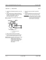
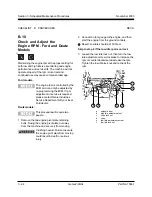
4 At the pre-filter, disconnect and plug the fuel
hose that goes to the fuel tank.
5 Disconnect the fuel hose from the fuel pre-filter
to the fuel pump. Remove the pre-filter.
6 Install the new fuel pre-filter and connect the fuel
hose between the fuel pump and the pre-filter.
Be sure the arrow on the pre-filter
is pointing towards the fuel pump.
7 Tag and disconnect the fuel hoses from the
pressure regulator/filter.
Explosion and fire hazard.
Electronic Fuel Injection (EFI)
systems operate at a very high
pressure. Fuel may be expelled
under pressure if the hoses are
removed too quickly. Loosen the
fuel lines very slowly to allow the
fuel pressure to dissipate
gradually. Wrap a cloth around fuel
hoses to absorb leaking fuel before
disconnecting them.
8 Remove the regulator/filter mounting fasteners
and remove the regulator/filter.
Summary of Contents for Z-60/34
Page 12: ...Genie Z 60 34 Part No 75861 November 2003 This page intentionally left blank ...
Page 157: ......
Page 160: ...Electrical Schematic Deutz F4L 1011F Models November 2003 Section 6 Schematics ...
Page 162: ...Ground Control Box Wiring Diagram Deutz F4L 1011F Models November 2003 Section 6 Schematics ...
Page 164: ...Platform Control Box Wiring Diagram Deutz F4L 1011F Models November 2003 Section 6 Schematics ...
Page 165: ......
Page 168: ...Electrical Schematic Ford LRG 425 EFI Models November 2003 Section 6 Schematics ...
Page 170: ...Ground Control Box Wiring Diagram Ford LRG 425 EFI Models November 2003 Section 6 Schematics ...
Page 173: ...November2003 Section 6 Schematics PartNo 75861 GenieZ 60 34 6 11 ...
Page 176: ...Hydraulic Schematic 2WD Models before serial number 4461 November 2003 Section 6 Schematics ...
Page 178: ...Hydraulic Schematic 4WD Models before serial number 4461 November 2003 Section 6 Schematics ...
Page 180: ...Hydraulic Schematic 2WD Models after serial number 4460 November 2003 Section 6 Schematics ...
Page 182: ...Hydraulic Schematic 4WD Models after serial number 4460 November 2003 Section 6 Schematics ...


