3 - 18
Genie Z-60/34
Part No. 75861
November 2003
Section 3 • Scheduled Maintenance Procedures
REV A
CHECKLIST
B
PROCEDURES
4 Open the ground controls side turntable cover.
5 Inspect the following areas for burnt, chafed,
corroded and loose wires:
· Inside of the ground control box
· Hydraulic manifold wiring
6 Start the engine from the ground controls and
raise the boom above the turntable covers.
7 Inspect the turntable area for burnt, chafed and
pinched cables.
8 Lower the boom to the stowed position and turn
the engine off.
9 Inspect the following areas for burnt, chafed,
corroded, pinched and loose wires:
· Cable track on the primary boom
· Cables on the primary, and jib booms
· Jib boom/Platform rotate manifold
· Inside of the platform control box
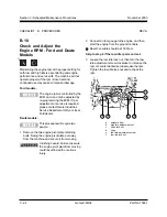
10 Swing the engine pivot plate in towards the
machine.
11 Install the bolts that were just removed into the
original holes to secure the engine pivot plate.
Crushing hazard. Failure to install
the bolts into the engine pivot plate
to secure it from moving could
result in death or serious injury.
B-2
Inspect the Electrical Wiring
Maintaining electrical wiring in good condition is
essential to safe operation and good machine
performance. Failure to find and replace burnt,
chafed, corroded or pinched wires could result in
unsafe operating conditions and may cause
component damage.
Electrocution hazard. Contact with
hot or live circuits could result in
death or serious injury. Remove all
rings, watches and other jewelry.
1 Open the engine side turntable cover.
2 Remove the two engine pivot plate retaining
bolts. Swing the engine pivot plate out away
from the machine and secure it from moving.
Crushing hazard. Failure to secure
the engine pivot plate from moving
could result in death or serious
injury.
3 Inspect the following areas for burnt, chafed,
corroded and loose wires:
· Engine wiring harness
· Hydraulic manifold wiring
Summary of Contents for Z-60/34
Page 12: ...Genie Z 60 34 Part No 75861 November 2003 This page intentionally left blank ...
Page 157: ......
Page 160: ...Electrical Schematic Deutz F4L 1011F Models November 2003 Section 6 Schematics ...
Page 162: ...Ground Control Box Wiring Diagram Deutz F4L 1011F Models November 2003 Section 6 Schematics ...
Page 164: ...Platform Control Box Wiring Diagram Deutz F4L 1011F Models November 2003 Section 6 Schematics ...
Page 165: ......
Page 168: ...Electrical Schematic Ford LRG 425 EFI Models November 2003 Section 6 Schematics ...
Page 170: ...Ground Control Box Wiring Diagram Ford LRG 425 EFI Models November 2003 Section 6 Schematics ...
Page 173: ...November2003 Section 6 Schematics PartNo 75861 GenieZ 60 34 6 11 ...
Page 176: ...Hydraulic Schematic 2WD Models before serial number 4461 November 2003 Section 6 Schematics ...
Page 178: ...Hydraulic Schematic 4WD Models before serial number 4461 November 2003 Section 6 Schematics ...
Page 180: ...Hydraulic Schematic 2WD Models after serial number 4460 November 2003 Section 6 Schematics ...
Page 182: ...Hydraulic Schematic 4WD Models after serial number 4460 November 2003 Section 6 Schematics ...


