Gen
i
us Gate Systems Ltd
4 Wayside Green Woodcote Reading Berks RG8 0QJ
Mail@Genius-Systems.co.uk
Directors: D.M.Pearson. M.J.Thornton. J.A.Pearson
Registration No: 4557960 (England)
V.A.T.No: 815 9757 88
Page 3
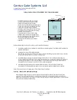
When finished remove the SIM (not forgetting to return the phone to its original memory setting) and
using the tip of a ballpoint or a similar small object eject the SIM tray from the top of the DMG at the
point shown by pressing the Yellow button as below:
SIM Tray
SIM Eject
button
SIM Tray
SIM Eject
button
3. Connect up the external components
Mount the DMG as desired and connect the antenna.
Note that the Antenna produces short range audio interference and should be kept at least 300mm
away from the audio gate panel if they are obliged to occupy the same cabinet.
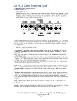
Connect the Audio circuits using the terminals marked. The COMmon terminals for the Mic and
Speaker for the voice circuits are the Left Hand ones of each pair. These may be connected together
if needed but best audio interference rejection is obtained if they are connected together at the
Voice panel only.
Next connect the Button inputs to the terminal strip as indicated. Note The DMG Button inputs
respond to being grounded via a dry contact only.
Next connect the relay outputs to the external drive circuits. Remember that Relay 2 is a Toggle.
Diagrams are available for most common industry analogue panels and can be found on our website.
Please contact us if you have a different panel and we will advise on compatibility.
4. Test the system
Check all connections and once satisfied power up the DMG1and the Gate panel.
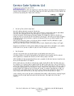
The Status indicator will start to flash quickly as the GSM unit tries to register with the network.
Once registration is complete the indicator will flash slowly (every 3 seconds).
NOTE the DMG will take approximately 80 seconds to complete its internal checks and read the data
stored on the SIM before it will respond.
With a mobile phone (or landline) call the phone number issued with the SIM. The DMG will answer
the call after 3 or 4 rings and issue a simple Dit-Dit-Dit Dee sound to the caller. The call will hold for
about 30 seconds as the internal countdown timer runs out, during which time the caller can operate
the relays by pressing button1 on the phone for relay 1, button 2 for relay 2 and so on. Each button
press will reset the countdown time to 30 seconds run time. Successful relay operation results in a
Dit-Dit-Dit-Dee sound being issued. The sound for relay 2 however also indicates the status of the
relay. Being a Dit-Dit-Dit-Dee-Dee as the relay closes and a Dit-Dit-Dit-Doh-Doh as it opens.
Let the call drop once proper operation is established and initiate outbound calls by pressing the gate
buttons to call the target numbers loaded into the SIM earlier. Once again check for proper
operation.

