Boot
ROM Usage and Memory
Address Setting
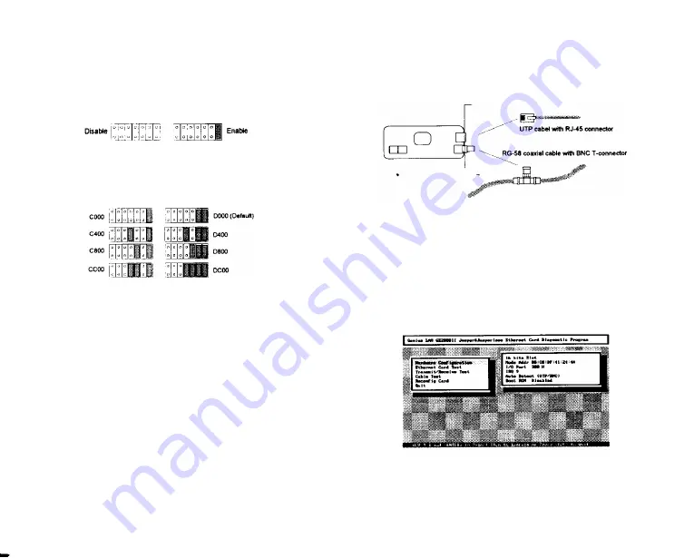
An optional boot ROM is available to be installed on the
6. Connect the adapter to the network using thin or twisted-
adapter. JP2 is by default set to Boot ROM disable. If a
pair Ethernet cable. (an optional AUI expansion port is
boot ROM is installed on the adapter, move the jumper to
available for thick Ethernet cable). A 50-ohm terminator
the appropriate address as the following figure shows.
(not supplied) is required when the BNC T-connector is
located at the end of a RG-58 coaxial cable segment.
JP2
Figure 10.
Boot ROM Usage setting
JP2
Figure I 1.
Memory Address Setting
Adapter Installation
In order to prevent any possible damage, please follow the
procedure below to install the adapter:
1. Turn off the power of PC and unplug its AC power cord.
2. Remove the cover of the computer’s chassis.
3. Plug the adapter into an available ISA bus slot.
4. Secure the adapter in the slot by tightening the screw on
metal mount to the back of the PC’s chassis.
5. Replace the cover of the PC’s chassis.
Figure 12. Network Installation
Adapter Diagnostic
In the main menu screen of the setup program, the user
could move cursor to Diagnostic, and press
[J]
to execute
adapter diagnostic program.
Figure 13. Adapter Diagnostic
2-4 2-5


