background image

5

ENGLISH

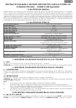
230 V~ (+6 -10%) - 50/60 Hz.

550 W
500 W

500 mA

-20°C +50°C

3

Adjustable using trimmer (from 10 to 120 sec.)

90 x 195 x 250 mm.

IP54

Power supply
Absorbed power
Max. motor load
Max. load on accessoies
Ambient temperature
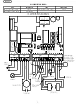
Protection fuses
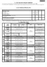
Operating logic

Opening /closing  time

Housing degree of protection (external)

Housing dimensions (external)

Functions selected with dip-switches

Terminal board outputs

Sensor connector

Radio control connector

Terminal board inputs

Thrust force

Pause time

Automatic / Semi-automatic /

Automatic with stop / Step-step with stop

Adjustable using trimmer (from  0 to 120 sec.)

Adjustable using trimmer

Total opening / Partial opening /

Closing photocells / Opening-closing limit switch /

STOP / Mains power supply  + Ground / Antenna

Radio receiver boards molex connector

Anti-crushing sensor

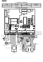
Accessory power supply 24 V~ / Flasher /

Gate status led / Motor

Operating modes

Closing photocell reaction

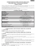
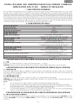
MICROPROCESSOR CONTROL UNIT FOR SLIDING GATES

USER INSTRUCTIONS - INSTALLATION STANDARDS

1. GENERAL FEATURES

Thanks to the high-power performance of its built-in microprocessor, this control unit for sliding gates offers a wide number

of services and adjustments. In addition, electronic power control guarantees a high safety level.

A sophisticated electronic control constantly monitors the power circuit and cuts off the unit when problems arise which

reduce the operating efficiency of the electronic clutch.

The main settings and operating modes can be defined using dip-switches while time and motor power adjustments are

performed using the trimmers installed on the electronic circuit board.

7 built-in LEDS constantly display the status of inputs, outputs in addition to any circuit malfunctions.

2. TECHNICAL FEATURES

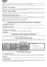
3. TERMINAL BOARD M1 (HIGH VOLTAGE) CONNECTIONS - DESCRIPTION

3.1  MAINS POWER

Terminals “1 - 2 - 3” (Live - Ground - Neutral), Power supply voltage 230 V~  50/60 Hz.

WARNING:

 the ground connection is mandatory to ensure proper unit operation.

4. TERMINAL BOARD M2 (HIGH VOLTAGE) CONNECTIONS - DESCRIPTION

4.1 FLASHER

Terminals “4 - 5” (Live - Neutral). Use a flasher with an operating voltage of 230 V~ (40W max.). When power is supplied to the

system the flasher will blink once to confirm that the unit is properly connected to the electric power supply.

4.2 GEAR UNIT

Terminals “6 - 7 - 8” (Close - Common - Open). Connect the motor and relative condenser.

WARNING: 

if the gear unit is incorrectly connected or the connection is not completed, the unit will be inhibited and this

status will be indicated by diagnostic 

LED 7

.

Notes:

1)

To install electric cables, us adequate rigid and/or flexible tubes.

2)

Always separate the low-voltage connection cables from the 230V~ power supply cables. Cables for the power

supply to the equipment must have a 1.5 mm

2

 section. To avoid interference, us separate sheathes.

3)

The box features 4 break-through holes Ø25 where Pg16 cable clamps with minimum protection degree IP54

must be mounted (not supplied).

5. TERMINAL BOARD M3 (LOW VOLTAGE) CONNECTIONS - DESCRIPTION

5.1 GATE STATUS LED

Terminals “9-10”. The signal led constantly displays gate status and motion. 

OFF

 = gate closed; 

ON

 = gate open;

SLOW FLASHING

 = gate opening; 

FAST FLASHING

 = gate closing.

Summary of Contents for JA277K

Page 1: ...ILS COULISSANTS CENTRAL DE MANDO CON MICROPROCESADOR PORTONES CORREDIZOS MIKROPROZESSOR STEUEREINHEIT F R SCHIEBETORE ISTRUZIONI PER L USO NORME DI INSTALLAZIONE INSTRUCTIONS FOR USE DIRECTIONS FOR IN...

Page 2: ...ny damage caused by improper use or different from the use for which the automation system is destined to 7 Do not use this device in areas subject to explosion the presence of flammable gas or fumes...

Page 3: ...h mentre le regolazioni dei tempi e della potenza del motore si effettuano tramite trimmer posti sulla scheda elettronica 7 LEDS incorporati indicano costantemente lo stato degli ingressi delle uscite...

Page 4: ...nte in funzione della programmazione effettuata tramite il dip sw4 Nota bene Per installare pi dispositivi di sicurezza collegare i contatti NC in serie Se non vengono utilizzati dispositivi di sicure...

Page 5: ...locca Pulse Nessun effetto APERTO IN PAUSA Reintegra la pausa Blocca ed inverte o blocca e al disimpegno inverte come da dip sw 4 Riapre immediatamente IN APERTURA Nessun effetto Blocca il funzionamen...

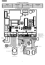
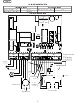
Page 6: ...e Accessori Logica 14 FUSIBILI DI PROTEZIONE 15 SCHEMA DI COLLEGAMENTO 230 V 50 60 Hz Lampeggiatore Motoriduttore Condensatore Blu Stop Led stato cancello Apertura totale Apertura parziale Altre sicur...

Page 7: ...switches while time and motor power adjustments are performed using the trimmers installed on the electronic circuit board 7 built in LEDS constantly display the status of inputs outputs in addition t...

Page 8: ...s Note If safety devices are not connected jump connect the input It is possible to prevent the gate from closing by connecting a 24h timer in series to the closing photocell circuit 6 TERMINAL BOARD...

Page 9: ...PING OPEN No effect Opens pauses and closes Re opens immediately Re closes immediately Re closes immediately No effect Blocks Pulse No effect Blocks operation Blocks and reverses or stops and starts a...

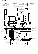
Page 10: ...Motor Accessories Logics 14 PROTECTIVE FUSES 15 CONNECTION DIAGRAM 230 V 50 60 Hz Flasher Geared motor Condenser Blue Stop Gate status led Total opening Partial opening Other safety devices Limit swi...

Page 11: ...upteurs positions multiples dip switch tandis que les r glages des temps et de la puissance du moteur sont effectu s par potentiom tre plac s sur la carte lectronique 7 LED incorpor es indiquent const...

Page 12: ...r 4 positions multiples Nota bene Pour installer plusieurs dispositifs de s curit connecter les contacts NF En s rie Il est possible de bloquer la refermeture du portail en connectant une horloge time...

Page 13: ...ffet Aucun effet Bloque Impulsion R ouvre imm diatement Referme imm diatement Ferme imm diatement Ouvre effectue la pause et referme Relance le temps de pause R ouvre imm diatement Ferme imm diatement...

Page 14: ...ique 14 FUSIBLES DE PROTECTION 15 SCHEMA DE CONNEXION 230 V 50 60 Hz Lampe clignotante Moto r ducteur Condensateur Bleu Stop Led tat du portail Ouverture totale Ouverture partialle Autres s curit s Fi...

Page 15: ...los tiempos y de la potencia del motor se efect an mediante trimmers elementos de ajuste los cuales se hallan en la tarjeta electr nica 7 LEDs incorporados indican de manera constante el estado de la...

Page 16: ...el movimiento de cierre El efecto es diferente en funci n de la programaci n realizada mediante el dip switch 4 Nota bien Para instalar varios dispositivos de seguridad conectar los contactos NC en se...

Page 17: ...sa y vuelve a cerrar Vuelve a abrir inmediatamente Vuelve a cerrar inmediatamente Vuelve a cerrar inmediatamente Cierra inmediatamente Cierra inmediatamente Bloquea el funcionamiento Vuelve a abrir in...

Page 18: ...sorios L gica 14 FUSIBLES DE PROTECCION 15 ESQUEMA DE CONEXIONADO 230 V 50 60 Hz Destellador Motorreductor Condensador Azul Parada Led de estado del p rton Apertura total Apertura parcial Otras seguri...

Page 19: ...n und Motorleistung mit dem auf der elektronischen Karte befindlichen Trimmer vorgenommen werden 7 eingebaute LED zeigen st ndig den Zustand der Eing nge Ausg nge und eventuelle Defekte des Kreislaufs...

Page 20: ...de Wirkung abgeben Die Wirkung ist von der Funktion der mittels Dip Switch 4 vorgenommenen Programmierung bedingt Anmerkung Zur Installierung von mehreren Sicherheitsvorrichtungen NC Kontakte seriensc...

Page 21: ...ofortiges Schlie en Blockiert Impuls Keine Wirkung Blockiert den Betrieb Keine Wirkung Keine Wirkung Blockiert Impuls Blockiert und kehrt um od blockiert und kehrt bei Freigabe um wie bei dip sw 4 ffn...

Page 22: ...Logik SCHUTZSICHERUNGEN 14 SCHUTZSICHERUNGEN 15 ANSCHLU SCHEMA 230 V 50 60 Hz Blinklampe Getribemotor Kondensator Blau Stop Torzu stand LED Teil ffnung Weitere Sicherheit svorrichtungen Endschalter Li...

Page 23: ...te fijado a la estructura de la cancela adem s de los dispositivos citados en el punto 16 18 GENIUS declina toda responsabilidad respecto a la seguridad y al correcto funcionamiento del equipo autom t...

Page 24: ...K aufwelchesichdieseerkl rungbezieht dennormen EN 50081 1 1992 EN 50082 1 1992 EN 60335 1 1994 entsprechen wieinderrichtlinievorgesehen EMC 89 336 CEE und ab nderungen 92 31 CEE und 93 68 CEE BT 73 23...

Reviews: