


17
FRANÇAIS
24 Vdc
3 W
C
M
24V
1 2 3 4 5 6 7 8 9 10 11 12
13 14 15 16 17
PE N L
EDGE
W.L.
TX-F
SW
+
LIMITS
ENCODER
MOTOR
ACCESSORIES
LAMP
MAIN
N
L
STOP
+
-
-
OPEN
B
A
OPEN
FSW
OP
FSW
CL
COM
OPEN
CLOSE
LAMP
PE
N
J1
J7
J5
J3
J6
24V
F1
F2
1 2 3 4 5 6 7 8 9 10 11 12
13 14 15 16 17
PE N L
ED
G
E
W.
L.
TX-
FSW
+
LIMITS
ENCODER
MOTOR
ACCESSORIES
LAMP
MAIN
N
L
F
+
RADIO
FCA
FCC
OPEN
B
FSW
CL
STOP
SAFE
OPEN
A
FSW
STO
P
+
-
-
OP
EN B
A
OP
EN
FSW
OP
FSW
CL
CO
M
OP
EN
CL
OSE
LAMP
PE
N
ENCODER
EDGE
OP
-
J1
J7
J5
J3
J6
J2
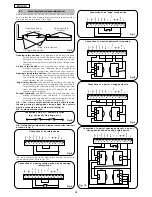
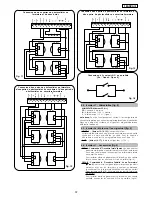
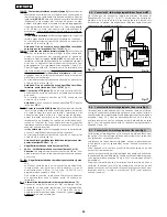
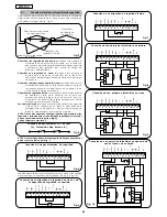
Fig. 1
Nota bene: Le condensateur est fourni avec l'opérateur.
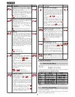
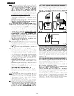
Fig. 2
OPEN TOTAL
OPEN PARTIEL
STOP
PLATINE ELECTRONIQUE JA383
DL
AFFICHEUR DE SIGNALISATION ET PROGRAMMATION
Led
LED DE CONTRÔLE DE L'ÉTAT DES ENTRÉES
J1
BORNIER BASSE TENSION
J2
CONNECTEUR DECODER / MINIDEC / RECEPTEUR RP
J3
CONNECTEUR ENCODEUR
J5
CONNECTEUR FIN DE COURSE
J6
BORNIER CONNEXION MOTEURS ET FEU CLIGNOTANT
J7
BORNIER ALIMENTATION 115 VCA
F1
FUSIBLE MOTEURS ET PRIMAIRE TRANSFORMATEUR (F 10A)
F2
FUSIBLE BASSE TENSION ET ACCESSOIRES (T 800mA)
F
POUSSOIR DE PROGRAMMATION "F"
–
POUSSOIR DE PROGRAMMATION "–"
+
POUSSOIR DE PROGRAMMATION "+"
F
F1
F2
J1
J2
J3
J5
J6
DL
–
+
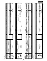
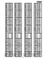
Tension d'alimentation
115 V~ - 50 Hz
Puissance absorbée
10 W
Charge maxi moteur
1200 W
Charge maxi accessoires
0,5 A
Température d'utilisation
-20 °C +55 °C
Fusibles de protection
2 (voir fig. 1)
Logiques de fonctionnement
Automatique / Automatique "pas à pas" /
Semi-automatique / Sécurité / Semi-automatique B /
Homme mort C / Semi-automatique "pas à pas"
Temps de fonctionnement
Programmable (de 0 à 4 mn)
Temps de pause
Programmable (de 0 à 4 mn)
Force de poussée
Réglable sur 50 niveaux
Entrées bornier
Open / Open partiel / Sécurités en ouv. /
Sécurités en ferm. / Stop / Bord / AlimeTerre
Entrées connecteur
Fin de course ouverture et fermeture / Encodeur
Sorties bornier
Feu clignotant - Moteur - Aliment. accessoires 24 Vcc -
Lampe témoin 24 Vcc/Sortie temporisée - Failsafe
Connecteur rapide
Embrochage platine à 5 broches Minidec, Decoder ou récepteurs RP
Programmation
3 touches (+, -, F) et afficheur, mode "base" ou "avancée"
Fonctions programmables mode base
Logique de fonctionnement - Temps
de pause - Force de poussée - Direction portail
Fonctions programmables mode avancé
Couple au démarrage - Freinage -
Failsafe - Pré-clignotement - Lampe témoin/Sortie temporisée -
Logiques sécurités d'ouverture et de fermeture -
Encodeur - Ralentissements - Temps d'ouverture partielle -
Temps de fonctionnement - Demande d'assistance - Compteur de cycles
Pour la connexion des
photocellules et des
dispositifs de sécurité, se
reporter au paragraphe 4.1.
BLEU
FIN DE COURSE
ENCODEUR
(en option)
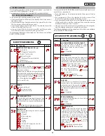
1.
AVERTISSEMENTS
Attention: Avant tout type d'intervention sur la platine électronique
(connexions, entretien), toujours couper le courant.
- Prévoir en amont de l'installation un disjoncteur magnétothermique
différentiel ayant un seuil d'intervention adéquat.
- Connecter la terre à la borne spécifique prévue sur le connecteur J7
de la platine (voir fig.2).
- Toujours séparer les câbles d'alimentation des câbles de commande
et de sécurité (poussoir, récepteur, photocellules, etc.). Pour éviter
toute perturbation électrique, utiliser des gaines séparées ou un câble
blindé (avec blindage connecté à la masse).
2.
CARACTERISTIQUES TECHNIQUES
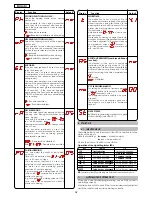
3.
SCHÉMA ET COMPOSANTS
Led
J7
4.
CONNEXIONS ELECTRIQUES
115 Vac
max. 60W
115 Vac
50 Hz
Summary of Contents for JA383
Page 23: ...note notes note notas anmerkung ...
Page 24: ...note notes note notas anmerkung ...
Page 25: ...note notes note notas anmerkung ...


