background image

11

Machine Debugging and Optimization


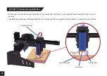
If engraved lines appear as jagged, please lower the travel speed (also known as feed rate), and repeat the test until the pattern is


normal. We suggest starting with a feed rate of no more than 1000 and working down from there until you get results that suit your


     needs.


If shapes like circles and squares appear to come out deformed,  start by trying to lower your travel speed and if the results do not 


improve, check the tension of your belts on the X and Y axis. If a belt is too loose, or too tight it can cause undesirable results. If


     you need to adjust the belt tension, please see the following instructions:

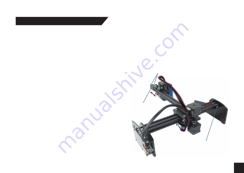
     - 

Loosen the tightness adjusting screw of the X-axis synchronous 


       belt and move the cover shell to adjust the tightness of the X-axis   
       synchronous belt.

     - 

Loosen the tightening adjusting screw of Y axis synchronous belt,      


and move the tightening adjusting screw of Y axis synchronous


       belt to adjust the tightness of Y axis synchronous belt.
     - Pay attention to ensure smooth movement of the machine in both    


 X and Y axes after tensioning the X and Y axis synchronous belts.   

       For best results try to make the tensions of each axis as equal as 
       possible.


Take care when working with clear or reflective materials such as 


acrylic or some metals. The laser will go straight through clear


     surfaces and engrave the area underneath and reflective surfaces  
     can damage the laser. In order to engrave these materials you will 
     need to cover with a layer of paint or something like painters tape. 


Depending on the material, you can use the black pen included


     in the package for this purpose.

Cover Shell

Y Axis Belt Tension 

Adjustment Buckle

Belt Tension 

Adjustment Screws

Summary of Contents for Jinsoku LE-1620

Page 1: ...V1 0 May 2021 USER MANUAL BENUTZERHANDBUCH Genmitsu Jinsoku LE 1620 Single Arm Laser Machine Jinsoku LE 1620 Einarmige Lasergraviermaschine Contents Inhalt English Deutsch 01 12 13 24 ...

Page 2: ...Package List Specifications Optional Accessories Not Included Assembly Overview Step 1 Step 2 Step 3 Step 4 Step 5 Machine Debugging and Optimization First Carve Tutorial 01 02 04 04 05 05 06 07 08 09 10 11 12 Contents ...

Page 3: ...aser unattended Fumes and smoke generated during the engraving cutting process must be extracted from the room as some can be poisonous make sure there is a ventilated system to the outdoors Make sure the cutting area under the laser is metal or non flammable Ensure that the room or area you are operating the laser in is sufficiently labeled to prevent someone from unknowingly walking into an acti...

Page 4: ...02 X Axis Module 1 Package List Y Axis Module 2 Laser Module 3 Wrench 2 5mm Wrench 3mm 4 5 Screws M5 30mm 3 6 Screws M3 6mm 5 7 Power Supply 12V 5A 8 Cable Tie 6 9 Power Line 10 ...

Page 5: ...03 USB A B Cable 11 USB Flash Disk 12 Goggles 13 Engraving Material MDF Board 100 100 9mm 2 15 Pen Black 14 Fixed Focal Column Φ16 20mm 16 Anti Skid Rubber Pads 5 17 Manual 18 ...

Page 6: ...Liftable height of laser head 50mm Working area 200mm Y 160mm X Dimension after installation 410mm 400mm 160mm Laser Rotary Roller MDF Board 04 Specifications Optional Accessories Not Included Natural Wood Slices LightBurn GCode License ...

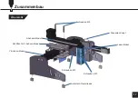
Page 7: ...05 Assembly Overview Y Axis Module X Axis Indentation X Axis Module M5 Screws Focusing Knob Laser Module M3 Screws M3 Screws Anti Skid Rubber Mat ...

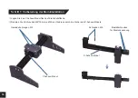
Page 8: ...ation Preparation Place the Y axis module flat on the desktop Take 2 M5 30 screws and insert them into the X axis module through the holes Y Axis Module Fixed Screw Holes M5 Screws Belt Tension Adjustment Screws X Axis Module ...

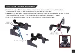
Page 9: ... groove of the X axis module screw it in and pretighten the fixing screw Align the two M5 screws of the X axis module over the M5 threaded holes of the carriage for the X axis module Insert the X axis module into the guide groove of the carriage Tighten the two fixing bolts to fix the X axis module and Y axis module X Axis Indentation Fixed Screw Holes X Axis Indentation ...

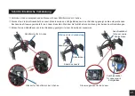
Page 10: ... the laser module to the focusing module with 4 M3 screws Remove the adhesive release paper from the anti skid rubber mat and install 4 Anti skid rubber pads as shown in the picture Anti Skid Rubber Mats Laser Module M3 Screws Focusing Module Anti Skid Rubber Mats ...

Page 11: ...e laser lead and cooling fan lead to the laser drive module as shown in the figure Observe the color coding of the two connection lines Tie the wire harness with the tie as shown in the figure X Axis Stepper Motor Tie Tie Wire Connection Complete Laser Line Laser Line Laser Line Laser Driver Board X Axis Stepper Plug Connect ...

Page 12: ...the laser head rise or fall so as to achieve the required focal length for engraving The focal length of the laser module is 20mm Use the supplied adjustment tool to focus the laser Laser Head Engraving Material Focal Length 20mm Fixed Focal Column Focusing Knob ...

Page 13: ...djust the tightness of the X axis synchronous belt Loosen the tightening adjusting screw of Y axis synchronous belt and move the tightening adjusting screw of Y axis synchronous belt to adjust the tightness of Y axis synchronous belt Pay attention to ensure smooth movement of the machine in both X and Y axes after tensioning the X and Y axis synchronous belts For best results try to make the tensi...

Page 14: ...pport is also available from our Facebook group SainSmart Genmitsu CNC Users Group Please scan the QR code to access a Quick Start Tutorial of the Jinsoku LE 1620 Single Arm Laser Machine https bit ly 3u4mFNR We suggest you to bookmark this link so that you won t miss any updated tutorials and resources of this machine ...

Page 15: ...onales Zubehör nicht im Lieferumfang Zusammenbau Übersicht Schritt 1 Schritt 2 Schritt 3 Schritt 4 Schritt 5 Fehlersuche und Optimierung der Einstellungen Erste Schritte mit der Lasergraviermaschine 13 14 16 16 17 17 18 19 20 21 22 23 24 Inhaltsverzeichnis ...

Page 16: ...nd des Gravier Schneidevorgangs entstehen müssen aus dem Raum abgesaugt werden da diese giftig sein können stellen Sie sicher dass ein Belüftungssystem ins Freie vorhanden ist Stellen Sie sicher dass der Schneidbereich unter der Lasergraviermaschine aus Metall oder einem anderen nicht brennbaren Material ist Stellen Sie sicher dass der Raum oder Bereich in dem Sie die Lasergraviermaschine betreibe...

Page 17: ... X Achsen Modul 1 Lieferumfang Y Achsen Modul 2 Laser Modul 3 Sechkantschlüssel 2 5mm Sechkantschlüssel 3 0mm 4 5 Schrauben M5 30mm 3 6 Schrauben M3 6mm 5 7 Netzteil 12V 5A 8 Kabelbinder 6 9 Netzkabel 10 ...

Page 18: ...Kabel 11 USB Speicherstick 12 Schutzbrille 13 Gravurmaterial MDF Platten 100mm 100mm 9mm 2 15 Stift schwarz 14 Einstellhilfe zur Fokussierung des Lasers Φ16mm 20mm 16 Antirutsch Gummipads 5 17 Benutzerhandbuch 18 ...

Page 19: ...bbare Höhe des Laserkopfes 50mm Arbeitsbereich 200mm Y 160mm X Maß nach Aufbau 410mm 400mm 160mm Laser Rotationswalze MDF Platten 16 Technische Daten Optionales Zubehör nicht im Lieferumfang Natürliche Baumscheiben LightBurn GCode Lizenz ...

Page 20: ...17 Zusammenbau Übersicht Y Achsen Modul Schlitten für X Achsen Modul X Achsen Modul Schrauben M5 Fokussier Knopf Laser Modul Schrauben M3 Schrauben M3 Antirutsch Gummipads ...

Page 21: ...n Legen Sie das Y Achsen Modul flach auf die Arbeitsfläche Nehmen Sie 2 Schrauben M5 30mm und führen Sie diese durch die Löcher des X Achsen Moduls Y Achsen Modul Gewindebohrungen M5 Schrauben M5 Einstellschrauben für Riemenspannung X Achsen Modul ...

Page 22: ...nut des Schlittens ein Überprüfen Sie ob das gesamte X Achsen Modul vollständig in der dafür vorgesehenen Führungsnut des Schlittens sitzt Wenn es nicht ordentlich sitzt oder verkanten ist überprüfen Sie alles auf Hindernisse und versuchen Sie es erneut Ziehen Sie die beiden M5 Schrauben an um das X Achsen Modul am Y Achsen Modul zu fixieren Schlitten für X Achsen Modul Schlitten für X Achsen Modu...

Page 23: ... das Laser Modul mit 4 Schrauben M3 6mm am Fokussier Modul Entfernen Sie die Schutzfolie von den selbstklebenden Antirutsch Gummipads und installieren Sie die 4 Antirutsch Gummipads wie in der Abbildung gezeigt Antirutsch Gummipads Laser Modul Schrauben M3 Fokussier Modul Antirutsch Gummipads ...

Page 24: ...teuerungsmoduls für den Laser Beachten Sie dabei die farbliche Kennzeichnung der beiden Anschlussleitungen Binden Sie den Kabelbaum wie in der Abbildung gezeigt mit einem Kabelbinder zusammen Schrittmotor für X Achse Kabel des Lasers Kabelbinder Kabelbinder Bild nach der Verkabelung Anschlusskabel für Laser sowie Kühlgebläse Anschlusskabel für Laser sowie Kühlgebläse Steuerungsmodul für den Laser ...

Page 25: ...h der Laserkopf hebt oder senkt um die gewünschte Brennweite für die Gravur zu erzielen Die Brennweite des Laser Moduls beträgt 20 mm Verwenden Sie die mitgelieferte Einstellhilfe zur Fokussierung des Lasers Laserkopf Gravurmaterial Einstellhilfe Brennweite 20mm Fokussier Knopf ...

Page 26: ...verschieben Sie die Abdeckplatte um die Spannung des Zahnriemens der X Achse einzustellen Lösen Sie die Einstellschraube des Zahnriemens der Y Achse und verschieben Sie die Abdeckplatte um die Spannung des Zahnriemens der Y Achse einzustellen Achten Sie darauf dass nach dem Spannen der Zahnriemen der X und Y Achse eine gleichmäßige Bewegung der Maschine in beiden Achsen gewährleistet ist Für beste...

Page 27: ...g erhalten Sie auch in unserer Facebook Gruppe SainSmart Genmitsu CNC Users Group Bitte scannen Sie den QR Code um ein Schnellstart Tutorial der einarmigen Jinsoku LE 1620 Lasergraviermaschine aufzurufen https bit ly 3u4mFNR Wir empfehlen Ihnen den nachfolgenden Link als Lesezeichen zu speichern damit Sie keine aktualisierten Tutorials und Ressourcen zu diesem Gerät verpassen ...

Page 28: ...rer nach dem Urheberrechtsgesetz erlaubter nicht kommerzieller Verwendungszwecke Für Genehmigungsanfragen wenden Sie sich bitte schriftlich an den Herausgeber All rights reserved This manual or any portion thereof may not be reproduced or used in any manner whatsoever without the written permission of the publisher except for the use of brief quotations embodied in critical reviews and certain oth...

Page 29: ...support sainsmart com www sainsmart com Vastmind LLC 5892 Losee Rd Ste 132 N Las Vegas NV 89081 Genmitsu Desktop CNC Laser ...

Reviews: