39
IT
MANUALE ISTRUZIONI
Rev. 01_05_2018
Serie Clinic 3
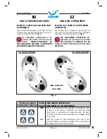
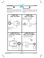
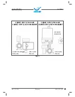
SICUREZZA
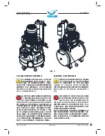
DISPOSITIVI DI SICUREZZA
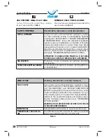
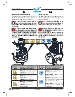
I dispositivi di sicurezza adottati sono i se-
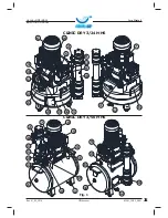
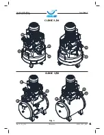
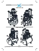
guenti (per i riferimenti sui disegni, vedere
pagine successive):
RIF.
DESCRIZIONE
FUNZIONE
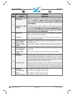
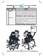
1
&XIÀDGLSURWH]LRQHYHQ
-
tola di raffreddamento.
ËXQDSURWH]LRQHÀVVDFRVWLWXLWDGDXQDJULJOLDLQPDWH
-
ULDOHSODVWLFRÀVVDWDFRQGHOOHYLWLDOODEDVHGHOJUXSSR
pompante bicilindrico. Serve ad impedire il contatto
accidentale con la ventola di raffreddamento in movi-
mento.
2
Termico ripristinabile.
È una protezione termica installata sull’impianto elettri-
co, che arresta il motore elettrico in caso di sovracca-
rico di corrente e/o cortocircuito. Il ripristino può essere
effettuato tramite il relativo pulsante.
3
Manometro pressione
serbatoio.
È un dispositivo di misurazione installato sul serbatoio del-
la macchina. Visualizza la pressione dell’aria compressa
all’interno del serbatoio (0 ÷ 10 bar).
4
Valvola di sicurezza.
ËXQDYDOYRODGLVLFXUH]]DFHUWLÀFDWDWDUDWDDEDU
installata sull’impianto pneumatico sotto al pressostato.
Serve a scaricare la sovrappressione dell’impianto qua-
lora il pressostato, per eventuali anomalie, non funzioni.
L’intervento della valvola di sicurezza obbliga l’operato-
re a spegnere la macchina e richiedere l’intervento dei
manutentori (vedi paragrafo “INTERVENTO VALVOLA DI
SICUREZZA”).
INSTRUCTION MANUAL
EN
MAN_CNC3_A001
SAFETY
SAFETY DEVICES
The Safety Devices adopted are as follows
(for the references on the drawings, please
see the pages down):
REF.
DESCRIPTION
FUNCTION
1
Cooling fan protection
KRRG
,WLVDÀ[HGJXDUGWKDWFRQVLVWVRIDJULGRISODVWLFPD
-
WHULDOÀ[HGZLWKVFUHZVDWWKHEDVHRIWKHWZLQF\OLQGHU
pumping unit. It prevents accidental contact with the
moving cooling fan.
2
5HVHWWDEOHWKHUPDO
It is a thermal protection installed on the electrical sy-
stem, which stops the electric motor in case of current
overload and/or short circuit.
Recovery can be done through the appropriate button.
3
Tank pressure gauge.
It is a measuring device installed on the tank of the ma-
chine. It shows the air pressure inside the tank (0 ÷ 10
bar).
4
6DIHW\YDOYH
,WLVDFHUWLÀHGVDIHW\YDOYHVHWDWEDULQVWDOOHGLQ
the pneumatic system under the pressure switch. It is
used to discharge the overpressure of the system if the
pressure switch, for any problems, does not function. The
intervention of the safety valve forces the operator to
turn off the machine and request the assistance of the
maintenance personnel (see par. “INTERVENTION OF
THE SAFETY VALVE”).
Summary of Contents for CLINIC 3/24
Page 77: ......

