23
9.1 Safety thermostat in electrical heater
(optional equipment)
If an error occurs on an electrical heater, the safety
thermostat will disconnect. The heater
is equipped with a fire thermostat that automatically cuts
off the power supply, if the temperature exceeds 50 °C.
If the temperature decreases, the heater automatically
re-engages. As an additional security there is a built-in
thermal cut-out, which disengages if the temperature
exceeds 100 °C. Re-engaging must be done manually.
Does not apply to PTC electrical heaters.
The system is not running. Unit stopped
Possible error
• Fuse in main board has blown, no power to unit.
• One of the fuses on the circuit board of the unit isblown.
• Loose wire, no power to unit.
• Loose wire between unit and control panel.
• Faulty or incorrectly set week program.
• Filter timer has switched the system off. Condensed
water is leaking from the unit Possible error:
• Condensation outlet blocked by dirt.
• The condensation outlet is not adequately protected
against freezing at low outdoor temperatures.
• If EB10 = on, check fans to ensure operation. If fans
are expected to run and RPM feedback = 0 then
ventilation unit will shut down and indicate alarm
No supply air
Possible error
• Faulty supply air fan
• Clogged supply air filter
• Clogged fresh air grill due to dirt and leaves during the
fall and snow and ice during the winter.
• Fuse on the circuit board is blown.
• The unit is in defrost mode (supply air fan stops)
No extract air
Possible error
• Faulty extract air fan
• Clogged extract air filter.
• Fuse on the circuit board is blown
Cold supply air
Possible error
• Clogged heat changer.
• Faulty extract air fan.
• Clogged extract air filter.
• Electrical reheater is disconnected at the over heating
thermostat (only units with electrical reheater installed).
• Air in the heating pipes, faulty thermostat / motorvalve,
incorrect setting of control panel.
Fans running full speed unintendedly
Check that EB9 is not set to m3/h when no flowsensors
have been installed. Ensure that EB9 is set to %.
With flowsensors installed in product – check that the duct
system is not blocked and that pressure drop is sufficiently
low (ventilation unit is not able to reach setpoint)
9.2 Error codes
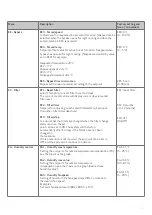
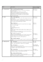
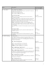
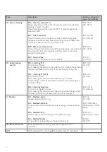
Error messages will be written in clear text on the Optima
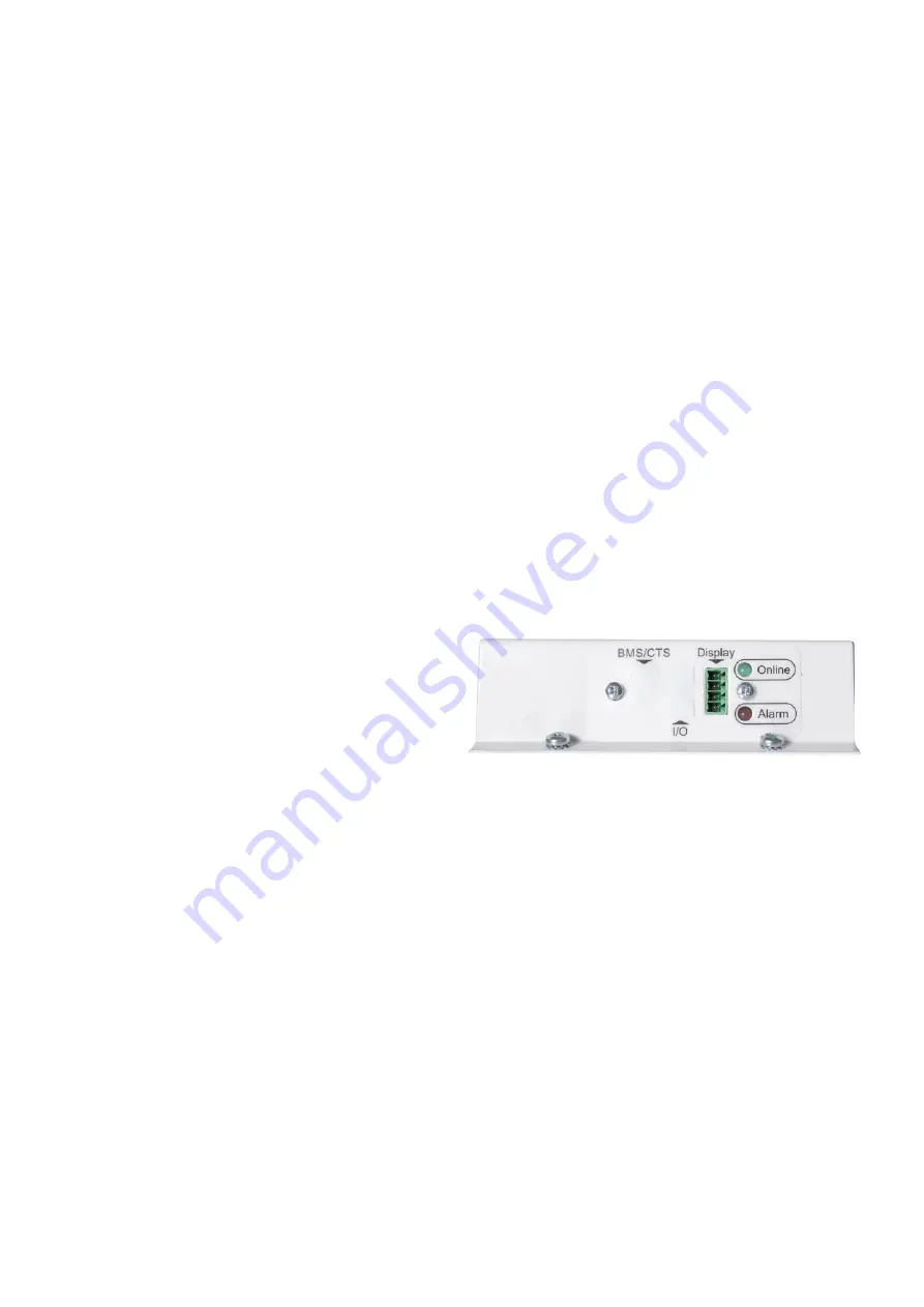
Touch display. When using only the the I/O connector PCB
and Optima Basic display – error messages will be displayed
with red flashes from LED 2.
Please refer to the table below for identification of errors.
LED 1: Online
Green light on = internet connection o.k.
Green light off = no internet connection
LED 2: Alarm
1 flash
= External stop
2 flashes = Sensor error
3 flashes = Humidity sensor error
4 flashes = Fan error
5 flashes = Sensor frost error
6 flashes = fire failure / test
7 flashes = fire failure – Damper 1
8 flashes = fire failure – Damper 2
9 flashes = fire failure – Box 1
10 flashes = fire failure – Damper 3
11 flashes = fire failure – Damper 4
12 flashes = fire failure – Box 2
Rotary heatexchanger operation status:
During operation of rotary heatexchanger the following
modes of operation can be read from the controller in the
Info/Operation Status menu.
Rotor status = 0 (Rotary heatexchanger not activated in
menu EC4)
Rotor status = 1 (Rotor stopped due to temperature
conditions activating night cooling or indoor/outdoor
temperature conditions too close)
Rotor status = 2 (Rotor running due to heatrecovery
demand)
Rotor status = 3 (Rotor running due to cooling recovery
mode active, indoor air temperature is colder than outside
air temperature)
Rotor status = 4 (Defrost mode, rotor speed reduced due to
defrosting of rotary heatexchanger)
9. TROUBLESHOOTING


