background image


 5

2.  PROGRAMMING THE OPTIMA 270  

CONTROLLER

The control system comes factory-preset, which means 

that the unit can be put into operation without changing the 

operating settings. The factory setting is only a basic 

setting that can be adapted to the operating desires and 

demands for the dwelling in question to make it possible to 

achieve optimal utilisation and operation for the system.

Depending on the product configuration it will be possible 

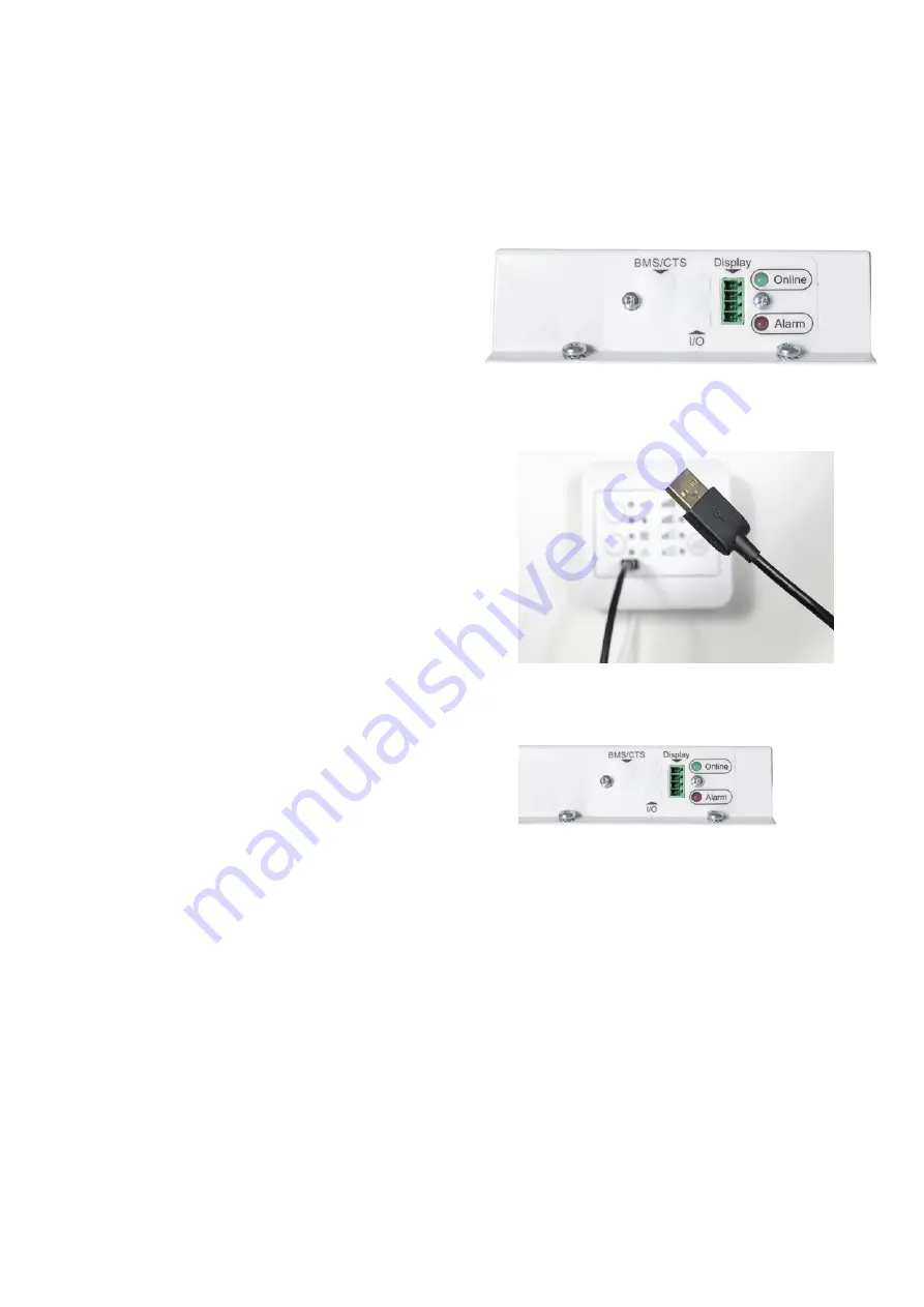
to either connect the Optima displays directly to the I/O 

connectors outside of the product (connectors marked with 

“display”) or directly on the PCB.

The I/O connection interface includes terminals for 

connecting both Modbus Master (for example building 

management systems) and Modbus Slave devices (for 

example district heating- or fire box PCB). To uncover the 

terminals, remove the dust protecting sticker gently.

2.1 Installations with no display interface

2.1.1. Connect an Optima Touch display to the Optima 270 

and adjust settings as necessary. Remove the Optima Touch 

display when the programming has been completed. The 

Genvex ventilation unit will continue to run according the 

the newly set parameters.

2.1.2 Use the Genvex PC tool to adjust the controller 

parameters. Connect a laptop to the controller via the 

Optima Basic or Touch display using the display as 

controller interfaces or connect directly to the micro usb 

connector on the PCB. 

The Optima Basic og Touch displays can be retrofitted to 

this type of installation if required.

2.2 Installation with Optima Basic display

See details in 1.0

2.3. Installation with Optima Touch display

2.3.1. Connect an Optima Touch controller to the Optima 

270 and adjust settings as necessary. 

NOTE: The Optima 270 controller parameters can be saved 

to the Optima Touch for 1 ventilation unit and be 

transferred to a similar system by using the “EA1 Save“ and 

“EA2 load settings”

The latest version of the Genvex Genlog software can be 

ordered from Genvex by tel45 73 53 27 00.

Summary of Contents for OPTIMA 270

Page 1: ...OPERATING INSTRUCTIONS OPTIMA 270 ...

Page 2: ...allation 3 2 Programming the Optima 270 controller 5 3 Displays 6 4 Start up 8 5 Controller menu 9 6 Controller settings 10 7 Further explanations of humidity and district heating control 21 8 Maintenance 22 9 Troubleshooting 23 ...

Page 3: ...s with a 4 wire twisted pairs 0 25 mm2 cable with a maximum length of 50 meters Fix the control panel to the enclosure using 4 screws as indicated on the picture Complete the installation by carefully clicking the plastic cover on top of the enclosure as indicated on the picture Note the display can be flush mounted in the wall by using an integrated euro norm socket To remove the display unclip t...

Page 4: ... wall Take the Optima Touch display which comes with a preinstalled wire connected and clip the display carefully on the fixture Ensure that the cable is carefully positioned as indicated on the picture before fitting the display NOTE if the preinstalled 1 8 meter length is not sufficient it is possible to replace this with a 4 wire twisted pairs 0 25 mm2 cable with a maximum length of 50 meters T...

Page 5: ...play interface 2 1 1 Connect an Optima Touch display to the Optima 270 and adjust settings as necessary Remove the Optima Touch display when the programming has been completed The Genvex ventilation unit will continue to run according the the newly set parameters 2 1 2 Use the Genvex PC tool to adjust the controller parameters Connect a laptop to the controller via the Optima Basic or Touch displa...

Page 6: ...er timer Push and hold for 10 seconds to clear errors and restart system Button C Push to change fanspeed If no LED indicators are on then fans are switched off Micro USB interface for PC programming of Optima 270 parameters LED light indicators LED light on indicate that function is enabled on LED light off indicate that function is disabled off LED light blinking indicate that function is active...

Page 7: ... alarms and eventlog menu Information bar indicating data and time If any errors have occurred these will be displayed here Touch to go back to go back to previous menu Touch to increase fanspeed to step 3 for 30 minutes time adjustable in menu A3 Touch to lock screen for 5 seconds time can be changed in menu D Using a 70 percent isopropyl alcohol wetted cloth you may gently wipe the exterior surf...

Page 8: ...he following information will be shown Please wait approximately 1 minute for the initial boot sequence to complete Software version controller actual software version of Optima 270 controller Software version display actual software version of display Device ID the ID of the internet connection secure protocol device in the controller IP adress will only be shown if the ventilation unit has been ...

Page 9: ...ngs B Scheduler calender schedules for change of fanspeeds and temperature setpoints C Date time date and time settings for info screen and for time stamping eventlog D Display settings related to display and access to parameters E Service service menu please note that this menu should primarily be used by technicians with knowledge of the machine operation 5 CONTROLLER MENU ...

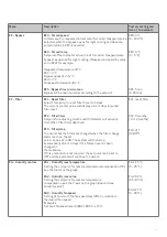
Page 10: ... you can enter how many hours the system should run on level 3 or 4 before it automatically returns to level 2 A5 3 hours 1 9 hours B1 Fan scheduler Here four seperate timers per day can be set for change of fanspeeds The scheduler can be adjusted seperately for each weekday if required If the same values shall be used for all weekdays the schedule can be copied by touching the buttin apply to all...

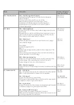
Page 11: ...update when the SD card containing the latest firmware has been inserted into the card reader to update the controller and display EA Save load settings EA1 Save settings Saves the settings from the Optima270 controller to the display EA2 Load settings Loads settings stored in EA1 and transfers data to a new Optima 270 PCB EB Fan speed levels EB1 Level 1 Supply air Level 1 which is the lowest spee...

Page 12: ...uires built in airflow sensors in the airhandling unit Please be aware that using this function without airflow sensors will lead to corrupted airflows Please note that fans will automatically adapt to increased pressuredrop for example clogged filters to maintain a constant airflow in this case increased fan power consumption is expected When selecting m3 h EB1 to EB9 will automatically allow dir...

Page 13: ...on extract air temperature sensor EC4 0 10 volt output selector Bypass PCB 0 10 volt output L11 is adapted to operate 0 10 volt bypass motor Rotor PCB 0 10 volt output L11 is adapted to operate rotoary heatexchanger Watervalve PCB 0 10 volt output L11 is adapted to operate 0 10 volt water control valve for waterbased reheater EC5 Help function Relay H17 Set point Function 0 The relay is off 1 The ...

Page 14: ...perature where the system should stop and the motor operated valve open completely for the flow of hot water EC9 System stop Here you choose if it should be possible to stop the system by selecting standby in fanspeed settings If the set point is OFF the system cannot be turned off If On is chosen then standby will be shown in fanspeed selector on main screen EC10 Right left model right MVHR confi...

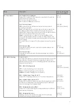
Page 15: ... country specific regulations on limitations when adjusting this function The modulating preheater function refers to the value adjusted in set point EC1 The preheater will try to maintain a steady freish air temperature according to this set point When the modulating preheater is used the existing fresh air temperature sensor T3 which is built into the ventilation unit can be used as reference No...

Page 16: ...C this menu item should be set to 3 C The bypass will open provided that 1 The extract air temperature is higher than the outdoor air temperature 2 The outdoor air temperature is above the set temperature in EE2 Units with modulating bypass If the temperature rises by 0 5 C above the requested temperature the bypass damper will begin to open The bypass is 100 open when the temperature reaches the ...

Page 17: ...erreset EF2 Filtertimer Setpoint for adjusting months until filteralarm will activate 0 months filtertimer deactived EF3 Filter stop To ensure that the filters are changed when the filter change alarm is active the set point can be set to ON The system will then stop automatically after 14 days if the filters have not been changed in the meantime If this precaution is not required the set point ca...

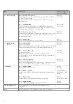
Page 18: ...ve energy for the rotor motor when there is limited possibility to recover energy EH3 Rotor max deicing time Setpoint in minutes for maximum time used for decicing rotary heatexchanger When exceeding the time limit the rotary heatexchanger will return to normal operation EH4 Rotor deicing pause Setpoint in hours corresponding to minimum time between deicing cycles EH1 10 rpm 0 25 rpm EH2 2 C 0 10 ...

Page 19: ...J4 Fire test hour Schedule for when automatic fire smoke damper test shall be conducted EJ1 0 0 4 EJ2 Off Off Test Reset EJ3 1 1 31 day EJ4 0 0 23 hour EK District heating PLEASE NOTE If no external outdoor air temperature sensor has been connected the controller the built in fresh air temperature sensor in the MVHR is used as reference for calculating weathercompensation temperature setpoints EK1...

Page 20: ... this value the controller will try to reach the setpoint temperature faster with a risk of overshooting the setpoint EK11 Heating PI I x10 PI controller I band By increasing this value the controller will try to reduce overshooting offset of temperatures with a risk of slowing the controller down EK12 Heating Reg time PI controller regulation time By increasing this value the controller will be s...

Page 21: ...ctived running in any other fanspeed mode Regulation of the fan speed takes place 1 for every 10 min factory setting EG4 The district heating control system will automatically adjust the flowtemperature of the heating system according to the outdoor air temperature The characterstic of the heating curve can be adjusted by EK2 and EK3 EK2 adjust the requested flow temperature at outdoor air tempera...

Page 22: ... into the condensation tray and make sure it runs off freely If the condensation drain does not work this could lead to water damage in the home Heat exchanger Inspect the heat exchanger every year If it is dirty remove it and Alu exchanger Wash in lukewarm soapy water and rinse using a hand shower if necessary Plastic exchanger No cleaning with solvents use only clean water carefully only careful...

Page 23: ...nnected at the over heating thermostat only units with electrical reheater installed Air in the heating pipes faulty thermostat motorvalve incorrect setting of control panel Fans running full speed unintendedly Check that EB9 is not set to m3 h when no flowsensors have been installed Ensure that EB9 is set to With flowsensors installed in product check that the duct system is not blocked and that ...

Page 24: ...n society as a whole a Genvex system actually allows you to recover up to 95 of the heat energy All Genvex systems have energy label A An original Genvex system is built by skilled experienced technicians and has a service life that in many cases is measured in decades Our units are approved according to all applicable standards and are also easy to operate and service on a daily basis Last but no...

Reviews: