background image

18


Optima 300

5. Function

5.1 Control system Optima 300 

Room regulation: 

The room temperature is controlled by the room sensor 

T2, which is fitted in the control panel. If a temperature 

of e.g. 21°C has been configured, the compressor will 

start when the room temperature falls to 20.6°C the 

compressor will stop when it has increased the room 

temperature to 21.4°C. If the compressor cannot maintain 

the room temperature, the motor-operated valve (devices 

with water after-heat surface) will begin to regulate (PI 

regulation) when the room temperature has fallen to 

20°C. 

For devices with electric after-heat surface divided into 

up to 4 levels, the first level will engage when the room 

temperature has fallen to 20°C. If the regulator time is set 

to e.g. 3 minutes, the room sensor will measure after 3 

minutes whether the room temperature is now above or 

below 20°C. 

Level 2 will engage if the temperature is still under 20°C. 

When the room temperature at some point reaches 

20°C, the electrical heat levels will begin to disconnect 

at 3-minute intervals. When the cooling (from +3°C to 

+10°C) starts, the diffusion and extraction fan engages 

at speed 3 and the cooling valve MA 7 opens so that 

the condenser on the diffusion side becomes a cooling 

surface and the cooling surface on the extraction side 

becomes a condenser.

When the room temperature has fallen 1°C, the 

compressor stops and the fan returns to normal 

operation. 

The cooling valve MA 7 only closes when the bypass 

function is closed.

If an extra cooling device is fitted to the system, this will 

engage when the room temperature is 2°C higher than 

start cooling.

Devices with an electrical pre-heat surface will regulate in 

the same way as an electrical after-heat surface. 

Defrosting


The device begins defrosting when the temperature 

difference between the temperature before the cooling 

surface and the cooling surface becomes too big, which 

occurs when ice forms on the cooling surface. 

The magnetic valve MA 4 opens, the diffusion fan and 

the electric heats surfaces stop until the ice is melted and 

the cooling surface has reached a temperature of about 

5°C, after which the magnetic valve closes again and the 

diffusion fan and electric heat surfaces start again. 

5.2 Extra capacity 

Electrical after-heat: 

If there is a greater requirement for heat that the unit 

can supply, the electric after-heat can be configured 

(additional equipment) to ON in the main menu with the 

shortcut key.

5.3 Operating reliability 

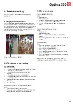
High pressure switch: 

In order to protect the compressor from running more 

than intended, a high pressure switch is built in that will 

disconnect when the pressure becomes too great. The 

red reset button on the pressure switch is activated in the 

cabinet when the cause of the fault has been found.

Overriding of the diffusion fan: 

If the diffusion temperature increases to over 45°C, the 

diffusion fan’s speed will begin to increase. 

The diffusion temperature will be maintained at 45°C if 

possible.

Overriding of the extraction fan:

If the discharge temperature for cooling increases to 

over 45°C, and the extraction speed at level 3 is not 

configured to 100 %, the extraction fan speed will 

begin to increase. The discharge temperature will be 

maintained at 45°C if possible.

Summary of Contents for Optima 300 DESIGN

Page 1: ...Version V1 02 0209 UK User Manual Optima 300 DESIGN ...

Page 2: ...dule for defrosting 16 4 6 Schedule for set points 17 5 Function 18 5 1 Controlling Optima 300 18 5 2 Extra capacity 18 5 3 Reliability 18 6 Connection to PC 19 6 1 Function description of data logger 19 6 2 Direct data logging 21 7 Maintenance 22 7 1 Unit 22 7 2 Alarms 22 7 3 Dismantling decommissioning the device 22 8 Troubleshooting 23 8 1 High pressure switch 23 8 2 The device is not running 2...

Page 3: ...under the glass screen You can use this to bring up the menu for daily control options simply by moving your hand past the control panel This function can be turned off See under Main menu Display Menu item 5 The following are located on the bottom of the control panel 1 SD card 2 Room sensor 3 Light sensor 4 Mini USB socket for connection to computer 1 The SD card which can be removed contains al...

Page 4: ...ings and tip it in against the wall At the bottom of the control panel there is access to A Terminal board Connection to main circuit board B SD card C Room sensor D Light sensor E USB port Fit a low voltage cable 4 x 0 25 mm between the unit and the control panel The maximum cable length is 50 m The voltage drop will be too great if the cable is over 50 m long and this may produce operational dis...

Page 5: ...y will now show Updating model Wait 1 5 minutes It takes approximately 1 5 minutes to read the current version Language load 91 Language OK Menu load 84 Menu OK Icon load 369 Menu OK Reset to default Restarting Optima 300 Then the display will then change to The symbol Bookmark Optima 300 Version number D Display 1 0 C Controller 3 0 Finally the display changes to daily operation and the device is...

Page 6: ...3 Use this function to turn on or off the supplementary after heat Use the button beside the after heat symbol to change between ON or OFF If the symbol is set at ON and the device is equipped with an after heat surface the after heat will commence as required If on the other hand the symbol is set to OFF the after heat will not commence even if it is required Temperature 7 Use this function to se...

Page 7: ...with the entered value in item 07 If the menu item is set to ON the brightness level of the screen saver will automatically regulate between the entered values in items 09 and 10 and when operating between the entered values in items 07 and 08 Both will depend on how dark the room is 07 Lightness day Use this to enter the maximum brightness for the control panel when the room is fully lit 08 Light...

Page 8: ...rent location Press Enter to access to the current menu s sub items Press Arrow down or Arrow up again to select the required menu item When the horizontal arrow is next to a menu point the 2 lines will change place the font size will change and the text Set will be added Pressing Enter next to the selected menu item will change the background of the item to grey Use the and buttons to change the ...

Page 9: ... third column S Use the fourth column to enter the temperature difference to which the temperature should be lowered Example If the temperature is set to 21ºC and you then enter 2 0º the device will aim at 19ºC If the speed has been changed manually on the button under daily operation the program will revert to the day program at the next change time point is passed Examples of a day program 01 07...

Page 10: ...filters are too dirty after the period configured configure the set point to a lower number If is not necessary to change the filter after the configured period the set point can be configured to a larger number When the timer reaches the configured value for the change of filter Alarm and Change filter will be flash at the top of the screen saver When the filters have been changed return to the s...

Page 11: ...ng surface T7 Air extraction T8 Water frost T9 Auxiliary sensors Press Arrow down to display the current speeds of the fans and the opening of the bypass valve and the opening of the water valve Supply air in Extract air in Bypass valve in Water valve in Press the Arrow down again to display the current status of the operation relays For extra electrical heat level R5 R6 and R7 an extra relay circ...

Page 12: ...t equipment and can be performed without the use of the main regulating valve Configuring the air volumes without expert advice is not recommended Incorrect configuration can lead to major energy consumption The default setting is 40 Item 11 Level 2 Supply air Level 2 is the recommended speed for the device to run in order to provide the optimal indoor climate and should be calibrated for the hous...

Page 13: ... ON in item 2 in the user menu the set point must be configured to the desired fresh air temperature to which the pre heat surface should heat the fresh air The temperature can be configured to between 15 and 0 C The default setting is 10 C Item 22 Regulation water If a water after heat surface with a motor operated valve is fitted to the device it may be necessary to adjust the regulation time Th...

Page 14: ...nt to OFF The device will stop if the set point is configured to ON Item 29 Stop defrosting The default setting is that the defrosting period ends when cooling service has reached a temperature of 5 C which is the default setting It may be necessary to change this temperature to a higher value in special operating conditions where the cooling surface is not completely defrosted The temperature can...

Page 15: ...er heat surface is fitted to the device you can decide when you want the after heat surface to operate If the set point is set to OFF the after heat service will not work even if it is required If the set point is set to OFF the after heat surface will engage as required It configures itself according to the temperature set in item 1 Item 38 Extra electric pre heat ON If an electric pre heat surfa...

Page 16: ...rs Mi nutes Speed Red T2 1 2 3 4 5 6 7 8 9 10 Thursday Hours Mi nutes Speed Red T2 1 2 3 4 5 6 7 8 9 10 Friday Hours Mi nutes Speed Red T2 1 2 3 4 5 6 7 8 9 10 Saturday Hours Minutes Speed Red T2 1 2 3 4 5 6 7 8 9 10 Sunday Red T2 Reduced room temperature 4 5 Schedule for defrosting Before cooling surface C Cooling surface C 15 5 14 5 13 5 12 6 11 6 10 7 9 7 8 8 7 8 6 9 5 10 4 10 3 11 2 12 1 12 0 ...

Page 17: ...19 Regulation form 0 0 2 20 Pre heat OFF ON OFF 21 Bypass open 10 15 0 22 Regulation water 20 1 250 23 Regulation electricity 3 1 30 24 Minimum air volume 30 0 100 25 Water frost 3 1 30 26 Water frost temperature 5 0 10 27 Help functions 0 0 5 28 Device stop OFF ON OFF 29 Stop detrosting 5 0 15 30 Compressor dif 0 4 0 1 1 0 31 Constant ON OFF ON OFF 32 Constant 5 0 10 33 Reduce the volume of fresh...

Page 18: ... fitted to the system this will engage when the room temperature is 2 C higher than start cooling Devices with an electrical pre heat surface will regulate in the same way as an electrical after heat surface Defrosting The device begins defrosting when the temperature difference between the temperature before the cooling surface and the cooling surface becomes too big which occurs when ice forms o...

Page 19: ...colours shown on the left hand side The exact time of the logging will be displayed in the field at the bottom Tip Click on the field for the clock to change the field to display LOG NO This can be useful if you want to refer to all of a specific logging At the top of the actual logging area on the screen there is an area with grey and white lines These lines will be red if an exit or function is ...

Page 20: ...ce menu displayed is protected with a password The password is not supplied Clock week program in control system Opens the box below In this box the clock program in Optima can be made in a simpler and clearer manner Select the day of the week to be programmed by clicking on it Monday has been selected in the example The clock program for Monday is selected using arrow up and arrow down in the low...

Page 21: ...ol system There is a risk therefore that analysis may be performed from a Combi but values are displayed as if they originate from an Energy If the logger circuit is removed from a panel to be read later a note should be made of the time This can be entered when taking readout from the software The software terminates in the event of a change of settings such as language or model This is not an er...

Page 22: ...to disequilibrium and cause a higher level of noise and also cause wear to the fans Air supply and extraction valves Clean the valves by drying with a dry cloth Take care that the valve does not turn around causing a change in air volume 7 2 Alarms Filter timer The control system has a filter timer in order to ensure that the filters are changed and optimal performance is maintained When the timer...

Page 23: ...st error Condensation water is leaking from the device Error Condensation outlet blocked with dirt The condensation outlet is not adequately protected against freezing at low outdoor temperatures 8 3 Error on air side No air supply to the rooms Error Defective fan Blocked bag filter Fresh air grill blocked with dirt and leaves in the autumn or snow and ice in the winter The fuse on the control sys...

Page 24: ...0 1 65 45 407 Fax 385 0 1 65 45 409 E Mail pichler zg hnet hr Denmark Genvex A S DK 6100 Haderslev Tel 45 73 53 27 00 Fax 45 73 53 27 07 E Mail salg genvex dk Germany Novelan GmbH D 95359 Kasendorf Tel 49 0 92 28 99 60 7 0 Fax 49 0 92 28 99 60 7 189 E Mail info novelan de Great Britain Total Home Environment Ltd GB Moreton in Marsh GL 56 0JQ Tel 44 0 845 260 0123 Fax 44 0 1608 652490 E Mail genvex...

Reviews: