background image

Service Manual FL 40-CrossPointer SP 

14 

4.3.


Assembly of the instrument


The  assembly  of  the  instrument  is  the  contrary  process  of  its  disassembly.  Jointing  of  each  screw  need  to 

rotate tightly, except for the situation that note especially. 


Requirement of assembly: 

a) Gelatinize 706 glue water on the jointing as follows: 

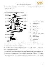
The interface between base

4-5

and inserting block

4-13


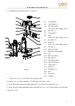
Lifting bracket

6-1

and press cover

6-21


Fine adjusting screw M6X10

3-11

and the main unit body 

b

Gelatinize 504 glue water on the jointing as follows: 

Gemel part

3-3

and pendulum

3-7


Locking ring 6

6-17

and gasket

6-18


Vertical window glass

1-7

and housing

1-2


Summary of Contents for Selection PRO FLG 40-PowerCross GREEN SP

Page 1: ...FL 40 PowerCross SP Service Manual...

Page 2: ...instrument 2 Accuracy calibration 2 1 Setting the reference 2 2 Sort of the error and calibration methods 3 Adjustment for alarming range 4 Disassembly and assembly of the instrument 4 1 Disassembly...

Page 3: ...The hairspring is broken 3 The 1 controling PCB is broken 1 Jointing the broken connecting line 2 Change the broken hairspring 3 Change 1 circuit board Laser line is dim The laser diode is broken Cha...

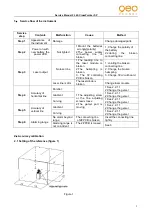
Page 4: ...adjacent light ruler to the right front of the adjusting platform the 0 position Of the adjacent light ruler should be consistent with the horizontal reference 0 position 2 2 Sort of the error and cal...

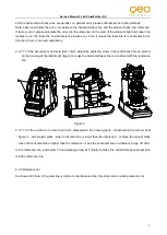
Page 5: ...10mm adjust the adjusting screw in two self check hole on point A on the housing of the instrument figure 3 make the horizontal laser line is coincident with the reference line Figure 3 2 2 1 1 2 If...

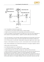
Page 6: ...figure 3 When adjust the two screws on point D it need to loosen one screw before tighten another screw until the horizontal laser line is coincident with the reference line The degrees of tightness o...

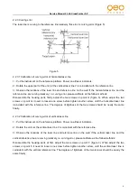
Page 7: ...one screw before tighten another screw until the horizontal laser line icoincident with the reference line The degrees of tightness of the two screws should be nearly the same finally 2 2 3 2 Calibrat...

Page 8: ...3 13 Then move 3 connecting PC board in horizontal make the alarming pole of 2 alarming PC board 3 13 locate in the centre of the alarming ring then fasten the screws When the incline degree of any di...

Page 9: ...th a cutter 1 1 2 Use a cross screwdriver to turn off 4 pcs cross head plate tapping screw ST2 2x5 1 4 and take off 1 operation PC board G609 1 operation PC board 1 3 3 Pull a little harder to move of...

Page 10: ...1 by a cross srewdriver move off 4 alarming PCB G609 4 alarming PCB 3 4 6 Screw off 1 pc of cross head plate screw M2X10 3 9 by a cross srewdriver move off horizontal laser module green laser module...

Page 11: ...ery cover part 4 9 3 Use electric iron to burn down the leading line of the power supply plug move off the contacting part 4 6 4 Screw off 3 pcs of nut M2 5 4 2 by a cross srewdriver move off 6 pcs of...

Page 12: ...board 6 15 6 1 Lifting bracket 6 2 Locking sheet 2 6 3 Damping bracket 6 4 Cross head plate tapping screw ST2 2X5 5 6 5 Locking ring 5 6 6 Cam 6 7 Cross head plate tapping screw ST2 9X9 5 9 6 8 Magne...

Page 13: ...the Locking ring 6 6 17 saperate turnplate 6 22 2 pcs of gasket 6 18 2 pcs of saddle pad 6 19 lifting bracket 6 1 7 Screw off 4 pcs of cross head plate tapping screw ST2 9X9 5 6 7 move off the base co...

Page 14: ...showed in figure 11 connect the corresponding connecting line to each PCBs accordingly Solder 4 hairsprings to the corresponding place of4 Alarming PC board or G609 4 Alarming PC board 3 4 and 3 Conne...

Page 15: ...that note especially Requirement of assembly a Gelatinize 706 glue water on the jointing as follows The interface between base 4 5 and inserting block 4 13 Lifting bracket 6 1 and press cover 6 21 Fin...

Reviews: