Service Manual FL 40-CrossPointer SP
2
1
、
Service flow of the instrument
2
、
Accuracy calibration
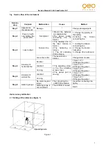
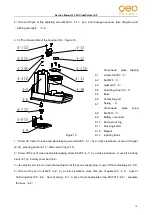
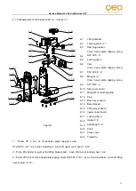
2.1 Setting of the reference (figure 1)
Figure 1
Service
step
Contents
Malfunction
Cause
Method
Step 1
Appearance
of
the instrument
Damage
/
Change damaged parts
Step 2
Power on with
new battery, the
power LED
Not lighted
1.Mount the batteries
wrongly(polarity)
2The power supply
connecting
line
is
broken
1. Change the polarity of
the battery
2.Jointing
the
broken
connecting line
Step 3
Laser output
No laser line
1.The leading line to
the laser module is
broken
2.The
hairspring
is
broken
3. The 1# controling
PCB is broken
1. Jointing the broken
connecting line
2. Change the broken
hairspring
3. Change 1# circuit board
Laser line is dim
The laser diode is
broken
Change laser module
Step 4
Accuracy of
horizontal line
Parallel
1.The adjusting screw
or the fine adjusting
screw is loose
2.The gamel part is
moving
1.See 2.2.1.1
2.Change the gemel
Gradient
1.See 2.2.1.1
2.Change the gemel
Curving
1.See 2.2.1.1
2.Change the gemel
Step 5
Accuracy of
vertical line
Gradient
1.See 2.2.1.1
2.Change the gemel
Curving
1.See 2.2.1.1
2.Change the gemel
Step 6
Alarming range
No alarm beyond
range
The connecting line
of2# PCB is broken
Insert the connecting line
tightly
Alarming range is
not coincident
The 2# PCB is loosed
See 3


