Page 28/48
© Geobrugg AG, CH-8590 Romanshorn, Switzerland
GBE-100A-R / 08
11
ASSEMBLY DETAILS
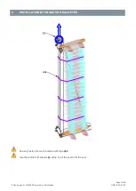
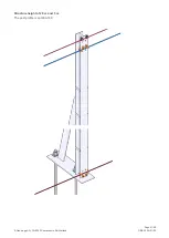
SETTING UP THE POSTS SECURELY
No one is permitted to stay in the fall zone of the posts any longer than necessary. Exercise extreme cau-
tion in this area until the posts are secured against falling forward or to the side.
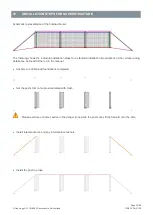
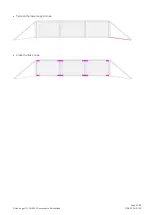
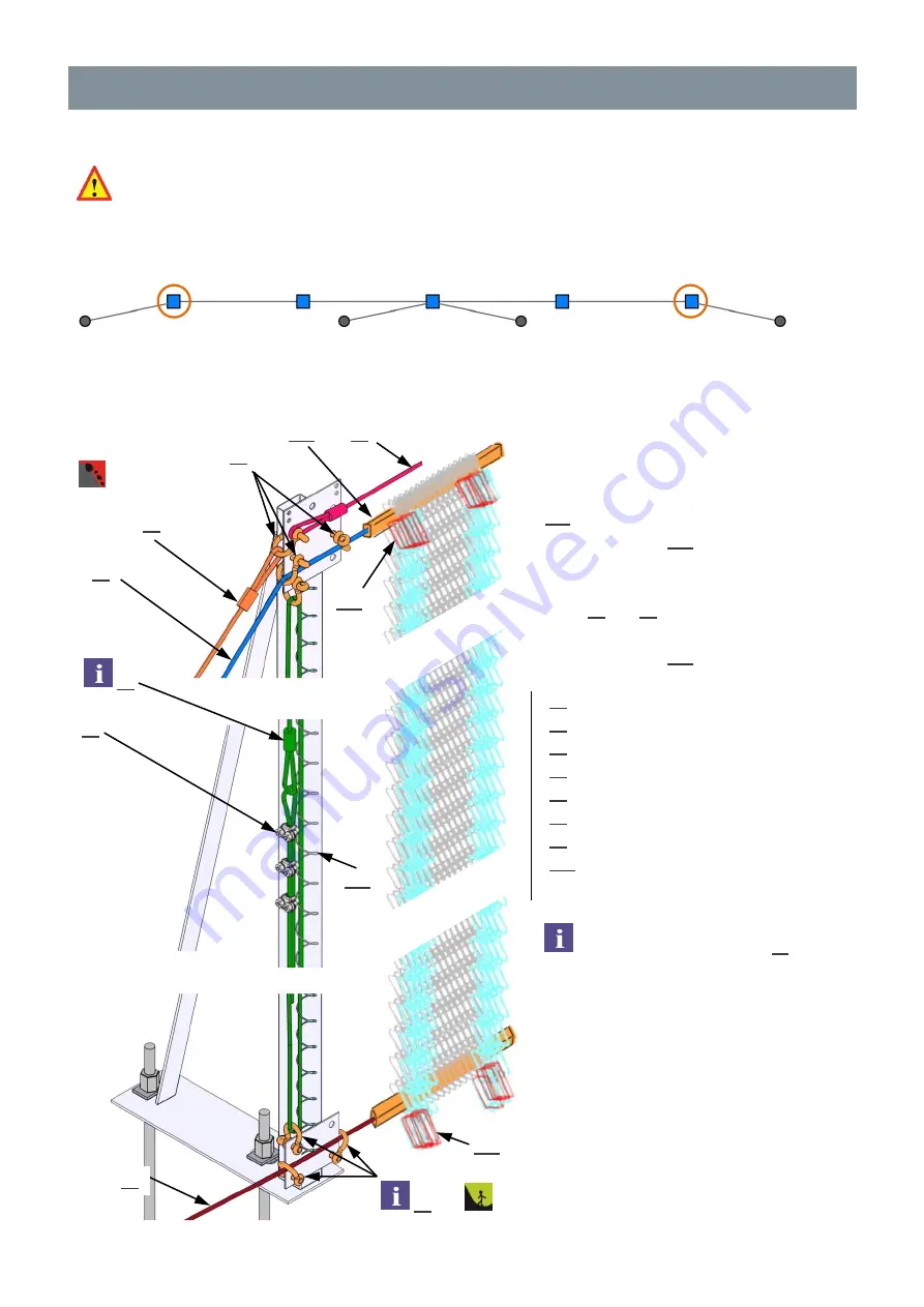
BORDER POSTS AND ROUTING OF THE SUPPORT ROPES THROUGH THE MESH
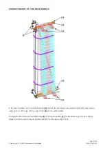
Structure height of 2 m
The post profile is a square hollow profile (RRW 90)
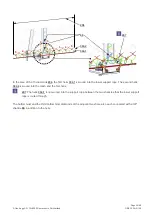
For the bottom 3 shackles
83
,
screw in the threaded bolt upslope
using the bolt head so that the mesh
or the horizontal helix springs do
not catch on the bolt head.
67
1 pc.
Lateralanchor rope
69
1 pc.
Vertical rope
71
1 pc.
Upper support rope
72
1 pc.
Lower support rope
77
1 pc.
Post top rope
83
7 pcs. 5/8" shackle
95
3 pcs.
7/16” wire rope clip
302
1 pc.
Helix XXXX x 64/4
– 100
See further on for details
83
72
69
95
83
67
71
302
77
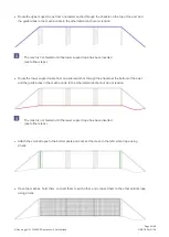
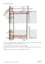
Flex zones are formed on both sides of
the posts (see "Flex zones" chapter).
The holes to be left free for this purpose
201
are already kept out of the way by
the guide profiles
202
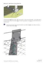
Outside of the flex zones, the support
ropes
71
and
72
are slotted through the
holes on the border directly by means of
the guide profiles
202
.
202
201
201
Summary of Contents for GBE-100A-R
Page 2: ...Page 2 48 Geobrugg AG CH 8590 Romanshorn Switzerland GBE 100A R 08...
Page 3: ...Page 3 48 Geobrugg AG CH 8590 Romanshorn Switzerland GBE 100A R 08...
Page 45: ...Page 45 48 Geobrugg AG CH 8590 Romanshorn Switzerland GBE 100A R 08...
Page 46: ...Page 46 48 Geobrugg AG CH 8590 Romanshorn Switzerland GBE 100A R 08...
Page 47: ...Page 47 48 Geobrugg AG CH 8590 Romanshorn Switzerland GBE 100A R 08...

