background image


Page 52/60 

© Geobrugg AG, Switzerland 

RXE-2000 / 11 

47


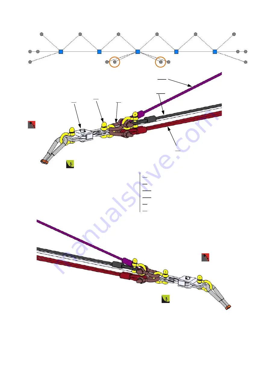
1x 

U-Brake U-300-R20 


72


2x 

Bottom support rope 

73.2

  1x 

Lower transmission rope 

78.2

  1x 

Lower U-Rope 

86


3x 

Shackle 1“, per Brake 

89


2x 

Shackle 1 1/4", per Brake 

73.2 

78.2 

89 

86 

47 

72 

TOP SUPPORT ROPE, UPPER U-ROPE AND UPPER TRANSMISSION ROPE ON ROPE ANCHOR 


Summary of Contents for RXE-2000

Page 1: ...European Technical Assessment ETA 13 1047 Date 28 02 2019 Edition 11 Geobrugg AG 8590 Romanshorn Switzerland Product Manual RXE 2000 ROCKFALL BARRIER...

Page 2: ...oof of quality assurance Staking out Assembly details System overview rope guide ISO 9001 certificate This document does not claim to be exhaustive It is designed for general standard applications and...

Page 3: ...The quality manual specifies in full the way in which the individual system components basic material commercial products and end products are checked extensively to eliminate poor quality You can fi...

Page 4: ...oning failure to use standard compo nents systems or original parts and corrosion caused by environmental pollution other human factors or other external influences As a contrast to the rockfall tests...

Page 5: ...ITH THE TERRAIN 10 5 STAKING OUT GEOMETRY 12 6 INSTALLING THE ROPE ANCHOR 16 7 ANCHORING THE BASE PLATE 18 8 PREPARING THE NETS AND POSTS 20 9 CRANE OR HELICOPTER ASSEMBLY 26 10 SUPERSTRUCTURE INSTALL...

Page 6: ...ownslope 1 HAZARD NOTES QUALIFICATION OF THE GROUP LEADER Only a qualified group leader may be put in charge of the installation TENSIONED ROPES Ropes will be tensioned When installing and pretensioni...

Page 7: ...nge 25 400 Nm see tightening torque required for wire rope clips and base plate fastening nuts Open ended wrench for base plate fastening nuts Felco C16 or C112 wire rope cutter or similar 12 mm cutti...

Page 8: ...e thimble For loops without a thimble the length h between the first wire rope clip and the point of load incidence must minimally be 15 time the nominal diameter of the rope In unloaded condition the...

Page 9: ...EOBINEX 7 8 5 150 330 32 A visible contusion of the wire ropes positively indicates that the wire rope clips have been tightened to the required tightening torque Undamaged wire rope clips may be reus...

Page 10: ...mportant to design the barrier line in a way that ensures it is as straight as possible and runs horizontally Ir regular lines as well as depressions and cambers in the terrain between the posts must...

Page 11: ...lengths h Height difference between two adjacent posts Tab 2 Distance between posts 6 8 m 8 10 m 10 12 m h 1 00 m 1 50 m 2 00 m No change required h 1 00 m 1 50 m 2 00 m Net must be adjusted In the e...

Page 12: ...ng on the terrain it may not always be possible to comply with the standard staking out measurements To ensure that the barrier still functions properly in these cases you may make several small adjus...

Page 13: ...20 3 00 7 00 10 50 2 35 11 90 3 50 7 50 11 30 2 50 12 80 3 75 1 If the terrain slope is less than 30 the distance of the upslope anchor ropes must be adapted and the length of the upslope an chor rop...

Page 14: ...oring has a rope diameter of d 22 mm INTERMEDIATE ANCHORING e T x 2 5 y 15 1 x 2 x 2 Length e see Tab 3 x Distance between posts y Angle of change in direction Anchor point T Downslope rope Intermedia...

Page 15: ...port rope separation must also be installed for intermediate anchoring purposes CHANGE IN DIRECTION TOWARD THE DOWNSLOPE In the case of changes in direction toward the downslope with an angle of more...

Page 16: ...out e g in the length of the upslope anchor ropes the angle between the upslope anchor rope and the post the incline of the base plate and so on The anchor bore holes are drilled in the direction of...

Page 17: ...Page 17 60 Geobrugg AG Switzerland RXE 2000 11...

Page 18: ...29 Mortar the anchor 05 in the loose ground 110 Fill in the concrete foundation 111 Tighten the fastening nuts 10 to approx 30 kN pretensioning force CONCRETE Can be used for all types of soil and ro...

Page 19: ...Tightening torque of the fastening nut for an anchor pretensioning force of approx 30 kN Swiss GEWI NG 28 Swiss GEWI NG 32 Tightening torque 400 Nm 400 Nm You must use mortar that is resistant to bot...

Page 20: ...red from left to right looking up S The net bundles are installed to the right of the posts as standard X In the event of significant height differences it is easier to pull the net down from the high...

Page 21: ...rows for control structure height h 4 m Row no 1 7 13 19 Marking for the various rows for control structure height h 5 m Row no 1 8 16 23 Marking for the various rows for control structure height h 6...

Page 22: ...termediate rings Number of rings depends on post distance Rings marked in blue a The U ropes are guided through 3 main rings on top and bottom of the net The 2 intermediate rings are fixed by shackles...

Page 23: ...ermediate rings Number of rings depends on post distance Rings marked in blue a The U ropes are guided through 3 main rings on top and bottom of the net The 2 intermediate rings are fixed by shackles...

Page 24: ...POSTS 33 3 pcs Running wheel 38 1 pc Clevis for 3 running wheels 40 1 pc Ringnet 16 3 350 52 1 pc Hex bolt M30x240 55 2 pcs Hex bolt M30 66 2 pcs Retaining rope 67 1 pc Lateral anchor rope 86 2 pcs Sh...

Page 25: ...ppropriate height between the rungs 204 and the post web The net bundle is connected to the assembly bracket and secured in place with straps 202 The top strap is fixed after the second row of rings 2...

Page 26: ...net bundle is secured in place with straps 202 To lift the edge posts use the middle 1 1 4 shackle 89 on the post head To lift the middle posts use the 1 shackle 86 of the U Brakes which are yet to b...

Page 27: ...on The corresponding details are described later Anchors are drilled and the foundations are completed Install overturn securing rope on the base plates Erect the posts preassembled with the ring net...

Page 28: ...x the U Brakes to the corresponding anchors Guide the top support ropes from one of the U Brakes to the other U Brake through the running wheels on the post head and the rings marked in red on the net...

Page 29: ...Guide the bottom support ropes from one of the U Brakes to the other U Brake through the running wheels on the base plate and the rings marked in red on the net bundle but do not tension them yet The...

Page 30: ...enings in the net bundle but do not tension them yet Shackle the edge rings of the net on the vertical rope Open fit and connect the ring net bundles under one another and shackle to the other vertica...

Page 31: ...rugg AG Switzerland RXE 2000 11 Tension the top U rope bottom support ropes lower U rope and the transmission ropes Feed vertical ropes F2 into the two edge nets Fix the secondary mesh strips upslope...

Page 32: ...Page 32 60 Geobrugg AG Switzerland RXE 2000 11...

Page 33: ...ea until the posts are secured against falling backward forward or to one side Long posts with preassembled net tend to lateral tip over Lateral guy ropes during installation prevent this Install the...

Page 34: ...110 57 2x Washer for M20 58 1x M20 hex head nut 66 2x Retaining rope 67 1x Lateral rope 68 1x Overturn securing rope 71 2x Top support rope 72 2x Bottom support rope 78 1 1x Upper U Rope 78 2 1x Lower...

Page 35: ...9 1x Vertical rope F1 70 2x Vertical rope F2 95 3x Wire rope clip 5 8 Before tensioning the lateral an choring 67 insert vertical rope F 69 around the shackle bolt and position the loop halfway up the...

Page 36: ...180 55 4x Hex nut M30 56 1x Hex bolt M20x110 57 2x Washer for M20 58 1x Hex nut M20 66 2x Upslope anchor rope 68 1x Overturn securing rope 71 2x Top support rope 72 2x Bottom support rope 78 1 1x Uppe...

Page 37: ...Page 37 60 Geobrugg AG Switzerland RXE 2000 11 01 1x Spiral rope anchor 66 2x Retaining rope 95 4x Wire rope clips 7 8 for each rope 95 66 01 UPSLOPE ANCHOR ROPES ON ROPE ANCHOR...

Page 38: ...Page 38 60 Geobrugg AG Switzerland RXE 2000 11 67 1x Lateral rope 97 5x Wire rope clip 7 8 per rope 97 67 LATERAL ANCHORING ON LEFT ROPE ANCHOR...

Page 39: ...97 78 1 97 97 47 1x U Brake U 300 R20 71 2x Top support rope 73 1 1x Upper transmission rope 78 1 1x Upper U Rope 86 2x Shackle 1 89 3x Shackle 1 1 4 97 4x Wire rope clips 7 8 for each rope TOP SUPPO...

Page 40: ...U ROPE AND LOWER TRANSMISSION ROPE ON LEFT ROPE ANCHOR 47 1x U Brake U 300 R20 72 2x Bottom support rope 73 2 1x Lower transmission rope 78 2 1x Lower U Rope 86 3x Shackle 1 89 2x Shackle 1 1 4 97 4x...

Page 41: ...ES In the case of the nets on the border posts 30 the transmission ropes are guided through the rings marked in red The 5 rings marked in blue are left free In the case of the nets on the middle posts...

Page 42: ...der posts through the cor responding ring row red For this purpose the first 5 rings of the net blue are left free The transmission ropes are not connected to the posts MIDDLE POSTS FINAL POSITION OF...

Page 43: ...are guided through the three blue colored main rings of the net In addition the blue colored intermediate rings in the corners of the net are fixed to both U Ropes 78 with 5 8 shackles 83 Furthermore...

Page 44: ...s of the net The upper U Rope 78 1 and the lower U Rope 78 2 are guided through the three blue colored main rings of the net In addition the blue colored intermediate rings in the corners of the net a...

Page 45: ...another two main ring rows meet To connect the two nets to one another the main ring of one net is pulled toward the next highest main ring of the other net and the two rings are connected with a 1 2...

Page 46: ...durch das Ringnetz an den Sch kel 1 86 gef hrt Die ersten 3 Ringe pink sind freigelassen die folgenden 4 Ringe schwarz sind in einem Winkel von ca 45 durchstossen danach sind die Seile vertikal durch...

Page 47: ...2000 11 INSTALLING THE SECONDARY MESH The wire mesh 221 is fixed to the ring net 220 with a double wire connector 222 Fastening takes place at each ROCCO Ring The wire mesh strips overlap one another...

Page 48: ...Page 48 60 Geobrugg AG Switzerland RXE 2000 11 97 79 1x Downslope rope 86 1x 1 Shackle 97 4x 7 8 Wire rope clips 86 79 86 79 97 INTERMEDIATE ROPE SUSPENSION DOWNSLOPE ANCHOR...

Page 49: ...Lower transmssion rope sec right 78 1 R 1x Upper U Rope sec right 78 2 R 1x Lower U Rope sec right 66 2x Upslope anchor rope 67 L 1x Intermediate anchoring section left 71 L 2x Top support rope secti...

Page 50: ...Page 50 60 Geobrugg AG Switzerland RXE 2000 11 NET RINGS AT RUNTOP ROPE AND RELEASED RINGS OF THE TRANSMISSION ROPES 97 213 214 97 213 214 71 L 71 R 73 1 L 73 1 R 73 2 R 73 2 L 74 1 212...

Page 51: ...e section right 97 2x 7 8 wire rope clip as connection of RUNTOP rope and one top support rope 212 Guide the RUNTOP rope through the ten blue colored rings Then fix it with a wire rope clip to one top...

Page 52: ...1x U Brake U 300 R20 72 2x Bottom support rope 73 2 1x Lower transmission rope 78 2 1x Lower U Rope 86 3x Shackle 1 per Brake 89 2x Shackle 1 1 4 per Brake 73 2 78 2 89 86 47 72 TOP SUPPORT ROPE UPPER...

Page 53: ...1 pcs Top U rope 86 6 pcs Shackle 1 89 2 pcs Shackle 1 1 4 97 1 pcs Wire rope clip 7 8 as connection for run top rope and top support rope 212 Bring the RUNTOP rope with the round clip to the shackle...

Page 54: ...un top rope 78 2 1 pcs Top U rope 86 5 pcs Shackle 1 89 2 pcs Shackle 1 1 4 97 1 pcs Wire rope clip 7 8 as connection for run top rope and top support rope 212 Bring the RUNTOP rope with the round cli...

Page 55: ...pe section left 78 2 R 1x Lower U Rope section right 86 4x Shackle 1 97 1x Wire rope clip 7 8 to connect the RUNTOP rope to one top support rope 212 The RUNTOP rope is guided through 5 blue rings on e...

Page 56: ...ent solutions in Switzerland the specifications of the Expert Commission on Avalanches and Rockfall EKLS must be complied with ROCK FACE CONNECTION If it is not possible to stake out in the standard w...

Page 57: ...s the correct number of rings been left free on the left and the right of the posts d Is the net fixed correctly to the support ropes and U Ropes e Is the number of wire rope clips at the rope end con...

Page 58: ...Page 58 60 Geobrugg AG Switzerland RXE 2000 11...

Page 59: ...Page 59 60 Geobrugg AG Switzerland RXE 2000 11...

Page 60: ...Page 60 60 Geobrugg AG Switzerland RXE 2000 11...

Reviews: