MODEL 6180 VERTICAL IN-PLACE INCLINOMETER SYSTEM
| INSTALLATION |
3
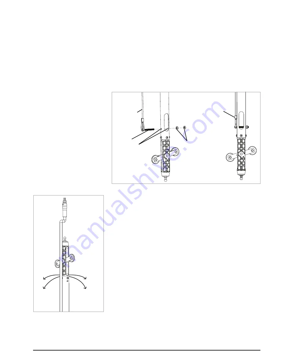
To connect the safety cable to the terminal sensor, complete the following steps:
1.
Fasten the upper end of the safety cable to a fixed object, or to something
too large to enter the casing, to avoid accidentally dropping the entire cable
into the casing.
2.
Remove the two hex nuts from the eye bolt.
3.
Insert the eye bolt through both connection holes on the terminal sensor.
4.
Thread the two nuts back onto the bolt and tighten against one another
using two 5/16" crescent wrenches; this will secure the safety cable to the
terminal sensor.
The figure below shows a properly connected safety cable.
3:
FIGURE 3:
Connecting a Safety Cable
5.
Tie off the top end of the safety cable by attaching it to an appropriate
anchor point. Follow the procedure from Section 2.5.1 for proper installation
of the cable clamps.
2.3
SENSOR ORIENTATION
All wheel assemblies should be oriented in the same direction when installed in
the casing. The wheel assemblies are attached at the factory so the upper wheel
is facing the A+ direction of the sensor (as shown in the figure to the left). Axis
directions are also physically labeled on each sensor.
Point the A+ direction in the same direction as the anticipated movement, i.e.,
towards the excavation being monitored or downslope for slope evaluation
applications.
The MEMS device monitors both A and B directions. The B+ direction is 90
degrees clockwise from the A+ direction, as viewed from above.
2.4
SENSOR INSTALLATION
The first sensor to install is the Model 6180T terminal sensor, which includes two
sets of wheels.
2.4.1 SUSPEND THE FIRST SENSOR
1.
Insert the 6180T sensor into the casing, making sure to orient the wheels
correctly for proper axis orientation (see Section 2.3), and with the male
cable connector facing up toward the top of the casing.
Safety Cable
Eye Bolt
Hex Nuts
Connection Holes
Connected
Safety Cable
4:
FIGURE 4:
A & B Directions
A- Direction
B+ Direction
A+ Direction
B- Direction


