6
| INSTALLATION | GEOKON
12:
FIGURE 12:
Cable Connection Detail
Note:
For additional security, tape the connectors together.
7.
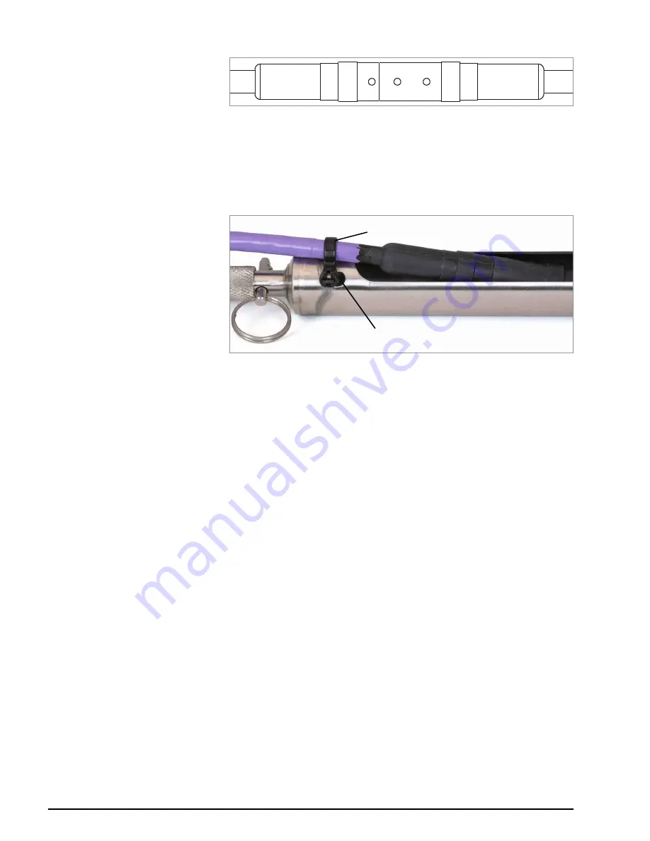
Using a provided tie wrap, secure the cable of the male connector to the
tube of the second sensor by feeding the tie wrap through the parallel slots,
around the cable, and back to itself; this will help provide strain relief for the
connectors. Trim any length of excess tie wrap. See the figure below.
13:
FIGURE 13:
Tie-Wrapped Cable
8.
Remove the screwdriver/rod from the first sensor and, with the safety cable
attached, lower the second sensor into the casing hole, until the ¼" support
holes are adjacent the top of the casing. Make sure to orient the A+
direction of each sensor correctly when inserting it into the casing.
9.
Suspend the second sensor in place at the top of the casing by inserting a
¼" diameter screwdriver or rod through the the support hole on the side of
the sensor.
10. Repeat steps 2 - 9 above for each subsequent sensor.
11. Plug the male connector of the top-most sensor to the female connector of
the readout cable (6180-3-1, 6180-3-2, or 6180-3V). Connect the other end
of the readout cable to the readout device or data-logger.
2.5
CONNECTING THE SUSPENSION BRACKET
To ensure the string is installed to the correct depth, sum the sensor lengths and
subtract this value from the desired string depth (measured from the top of the
casing to the bottom of the string assembly); the resulting value is the
Suspension Cable Length.
Note:
GEOKON
suggests suspending the sensor string at least 150 mm (six
inches) above the bottom of the casing, to account for debris and settlement.
2.5.1 CONNECT THE CABLE ASSEMBLY TO THE BRACKET
1.
Hook the supplied thimble through the bottom-side eyelet on the
suspension bracket (6180-2).
2.
Feed the bare cable end of the suspension cable assembly (6180-1) through
the bottom-side eyelet on the suspension bracket.
Tie-wrap
Slot


