3
3. GETTING STARTED
This section will outline the basic steps needed to install the communications software, establish
communication with the Model LC-2 and configure the datalogger in the context of water level
monitoring using a Geokon model 4500S Vibrating Wire Pressure Transducer.
The following equipment will arrive with the Model LC-2 datalogger:
•
Set of two alkaline D cell batteries.
•
Set of four desiccant packs packaged with the batteries.
•
Set of two screwdrivers, one Phillips Head and one Flat Head.
•
9-pin Dsub to 10-pin Bendix RS-232 cable (included with models 8002-1-1, 8002-1A-1), or,
USB-A to 10-pin Bendix USB cable (included with models 8002-1-2, 8002-1A-2).
•
Model LC-2 Single Channel Datalogger Instruction Manual.
The following are optional accessories:
•
RS-485 interface cable(s).
•
S-8001-5 or S-8002-5 RS-485 computer interface.
•
Vibrating Wire Sensor with built-in thermistor.
If any of these items are missing or damaged, contact the factory for replacements.
3.1 Transducer Installation
3.1.1
Cable Gland Models (8002-1-1, 8002-1-2, 8002-1-3)
1)
Open the datalogger by unscrewing the four captive screws on the front of the
enclosure.
Make sure that no dirt, water or other contaminants are allowed to
enter the enclosure.
2)
Loosen the nut on the cable fitting and remove the white plastic dowel.
3)
Thread the transducer cable through the cable fitting.
4)
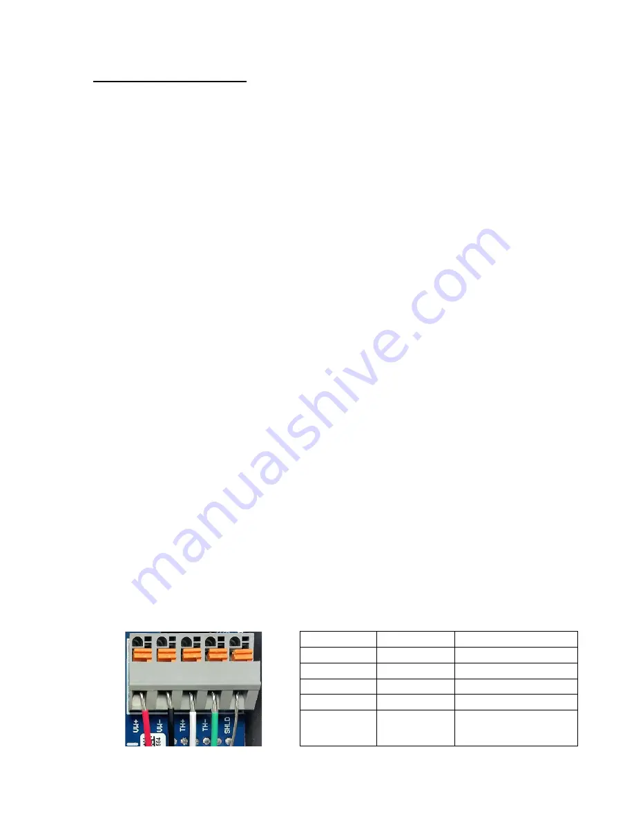
Wire each conductor of the cable into the correct position in the terminal block by
pressing down on the corresponding orange tab at the back, inserting the conductor,
and then releasing the orange tab. Refer to Figure 1 and Table 1 for transducer wiring
information. (See also Appendix B.)
Position
Color
Description
VW+
RED
Vibrating Wire +
VW-
BLACK
Vibrating Wire -
TH+
WHITE
Ther
TH-
GREEN
Thermistor -
SHLD
BARE
Analog Ground
(shields)
Table 1 - Transducer Wiring
Figure 1 - Terminal Connections


