background image

Premium 

1.56DOF/1.5HF6DOF

Device Guide

Summary of Contents for Geomagic Phantom Premium 1.56DOF

Page 1: ...Premium 1 56DOF 1 5HF6DOF Device Guide ...

Page 2: ...re usage guidelines are provided to assist the user in protecting the effectiveness and life of the device They are not intended as recommendations for the prevention of repetitive stress injury carpal tunnel syndrome or any other conditions injuries or disorders users should consult their own physicians By using the Phantom device the user acknowledges and agrees that Geomagic shall have no liabi...

Page 3: ...m Device 2 1 Run Phantom Test to Verify Setup 2 3 Chapter 3 Using the Phantom Premium Device 3 1 Working in 3D Space 3 1 Use Caution when Using the Phantom Premium Device 3 1 Physical Limits of the Device 3 2 Using the Motors 3 2 Appendix Troubleshooting A 1 Appendix Customer Support B 1 Appendix Regulatory Notices C 1 Appendix Maximizing Positioning Accuracy D 1 Appendix Configuring Multiple Devi...

Page 4: ...Premium 1 56DOF 1 5HF6DOF Device Guide ...

Page 5: ...ivers install and work smoothly If you experience any problems in the installation or use of your device please contact Customer Support see inside cover for contact information Please note if you are installing your device on a supported non Microsoft Windows OS you will find additional information in a separate document that shipped with your software product Typographical Conventions This guide...

Page 6: ...ii Premium 1 56DOF 1 5HF6DOF Device Guide PREFACE ...

Page 7: ...er handling troubleshooting and device specifications The Phantom Device Driver Installation Guide Describes the process of installing the device drivers Parallel Port Cable This cable is used to attach the computer s parallel port to the Phantom Premium or one unit to another The cable is an IEEE 1284 EPP cable with a ferrite bead that provides an impedance at 100mhz of 199 ohms or greater Univer...

Page 8: ...ble stylus for end user customization Integrated momentary switch on the stylus for ease of use and end user customization Constructed of metal components and injection molded plastics System Requirements The Phantom Premium haptic device requires certain hardware and software components to be able to function properly This sections describes the requirements for operating the Phantom Premium hapt...

Page 9: ... damage to the device from a direct unintentional elbow hit Remember Do NOT attempt to lift the unit or relocate it on the desk by pulling on the stylus This may result in severe damage to the device Positioning the Phantom Premium Device The correct placement of the device will vary from one user to another You may want to experiment to find a placement that feels right for you The device should ...

Page 10: ...1 4 Premium 1 56DOF 1 5HF6DOF Device Guide 1 GETTING STARTED Proper Handling and Positioning of the Phantom Premium Device ...

Page 11: ...r installing the PDD on Windows XP Vista and Windows 7 operarting systems can be found in the Phantom Device Driver Installation Guide For installation instructions for other operating systems see the additional documentation shipped with your device or software product or contact customer support Note As with most other software packages you must have administrator privileges on the machine in or...

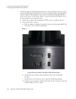
Page 12: ...e Phantom Premium device or the other peripherals to the additional card 1 Restart your computer after installing the PDD if you have not already done so 2 Connect the cables as follows a With the computer still turned off attach the male end of the supplied IEEE 1284 rated cable to your computer s parallel port FIGURE 1 Connect the power cables to the back of the Premium device b Plug the female ...

Page 13: ...est application to confirm that the device is properly connected and installed 1 Select Start All Programs Sensable Phantom Test 2 Put the Phantom in neutral position Neutral position is described as when the 4 rotary joints are lined up See Appendix D Maximizing Positioning Accuracy for more information about position accuracy 3 You can press the space bar on your keyboard to reset IMPORTANT Geom...

Page 14: ...1 4 Premium 1 56DOF 1 5HF6DOF Device Guide 2 INSTALLING THE PHANTOM PREMIUM DEVICE Run Phantom Test to Verify Setup ...

Page 15: ...hallenging and were often frustrated as they learned If you are new to working in 3D digital space and haptics working with the Phantom Premium device may take a little getting used to Understanding where objects are in 3D space may take some practice before you are able to move and manipulate objects with ease and certainty Be patient with yourself Use Caution when Using the Phantom Premium Devic...

Page 16: ... Premium device will pivot until is reaches a physical limit Again do not try to force the device past any of the mechanical stops b Next move the stylus up down The primary movement will happen in the shoulder of the Phantom Premium device c Next move it in out with the primary movement happening in the elbow When you reach a physical limit you ll feel one of the device s mechanical stops Don t f...

Page 17: ...d to cut off the power to the three gimbal motors which are responsible for rotational torque feedback When the switch is in the ON position the motors and encoders are bothe connected When the switch is in the OFF position the encoders are still powered but the motors are not These are handy features for debugging new haptics code ...

Page 18: ...1 4 Premium 1 56DOF 1 5HF6DOF Device Guide 3 USING THE PHANTOM PREMIUM DEVICE Using the Motors ...

Page 19: ... or email SensableSupport geomagic com When contacting Support you may be asked to run the Phantom Test application to help with diagnosis This application can be found in the directory where you installed the Phantom Device Drivers or via the Start All Programs Sensable menu The following describes the basic features of this test application which you should be prepared to run Select the Phantom ...

Page 20: ...A 2 Premium 1 56DOF 1 5HF6DOF Device Guide APPENDIX TROUBLESHOOTING ...

Page 21: ...ly You must return the device for servicing If you encounter any difficulties within your warranty period you can obtain Technical Support through the three channels listed below If you are out of warranty and do not have active maintenance Technical Support is limited If you purchased your Phantom Premium device from a distributor please contact them first Customer Support can be reached via e ma...

Page 22: ...B 2 Premium 1 56DOF 1 5HF6DOF Device Guide APPENDIX CUSTOMER SUPPORT ...

Page 23: ...t off and on the user is encouraged to try to correct the interference by one or more of the following measures Reorient or relocate the receiving antenna Increase the separation between the equipment and receiver Connect the equipment into an outlet on a circuit different from that to which the receiver is connected Consult the dealer or an experienced radio TV technician for help Modifications n...

Page 24: ...is to certify that the Geomagic Phantom Premium haptic devices are shielded against the generation of radio interference in accordance with the application of Council Directive 89 336 EEC Article 4a Conformity is declared by the application of EN 55022 Class B CISPR 22 Warning These are Class B products In a domestic environment this product may cause radio interference in which case the user may ...

Page 25: ...the endpoint position implies an absolute knowledge of the joint angles However incremental encoders can only provide angular measurements relative to the joint angles at which the system woke up at initialization time To obtain absolute angular measurements the system must initialize at a known position and orientation often referred to as neutral position Initialization position for Phantom Devi...

Page 26: ...essary to create a fixture to ensure accurate and repeatable system initialization The answer to that question depends greatly on the application The following figure shows typical positioning errors when the initialization position is translated from the optimal startup position by an eyeballing error of 0 2 in the x and z directions The best case error is around the initialization point with the...

Page 27: ...IMIZING POSITIONING ACCURACY Onthe other hand for applications in which position is critical such as teleoperation 3D digitization or operation of two Phantom s in the same virtual space it is generally advisable to create a jig for accurate initialization ...

Page 28: ...D 4 Premium 1 56DOF 1 5HF6DOF Device Guide APPENDIX MAXIMIZING POSITIONING ACCURACY ...

Page 29: ...nu open the Control Panel Select Phantom Configuration The Phantom Configuration window opens 2 On the hardware tab click Add 3 Enter a name to call that device click OK 4 From the Phantom model menu select the correct model 5 Click OK Dual Configurations The Dual Configuration settings only apply if you want to set up a pair of Phantom devices to work in tandem with each other You must have creat...

Page 30: ...E 2 Premium 1 56DOF 1 5HF6DOF Device Guide APPENDIX CONFIGURING MULTIPLE DEVICES ...

Page 31: ... screw Be careful not to tighten it too much it could strip the threads and or mar the shaft 6 Pass the 26 pin connector between the upper and lower arms in the arm assembly 7 Plug the 26 pin connector into the socket located on top of the Phantom Premium 8 Using the small cable ties included fasten the cable to the mechanical arm so that the cable will not interfere with the movement of the Phant...

Page 32: ...ght being careful to avoid the motor driver wires The counterweights should be perpendicular to the Phantom Premium s arms The counterweights should be approximately 1mm away from the motor mount in the motor axis direction You may have to bend the motor driver terminals to 60 away from the motor to make room for the counterweights do this carefully Insert and tighten two 8 32 screws to secure the...

Page 33: ...w part number 01509 located near the end of the last link 6 Pull the encoder gimbal assembly out of the last link The gimbal should slide out with a minimal amount of force 7 Hold both counterweight pieces in one hand to avoid dropping them Using a 9 64 hex key part number 01629 remove the two screws in the counterweights and remove the counterweights 8 Insert the bare shaft of the thimble gimbal ...

Page 34: ...F 4 Premium 1 56DOF 1 5HF6DOF Device Guide APPENDIX INSTALLING REMOVING THE ENCODER GIMBAL ...

Page 35: ...d i x Appendix Power Specifications With Internal Auto Switching Power Supply Output Current Rating 8 3 A AC Input 100 120 VAC 200 240 VAC auto switching power supply Input Frequency 50 60 Hz AC Current 5A 115V 2 5A 230 V Inrush Current 15A 115V 30A 230 V ...

Page 36: ...G 2 Premium 1 56DOF 1 5HF6DOF Device Guide APPENDIX POWER SPECIFICATIONS ...

Page 37: ...tors will not work with OpenHaptics v2 0 Windows XP Vista or Windows 7 32 or 64 bit Specifications Range of Motion 0 to 30 degrees Digital Encoder 2 linearity potentiometer Force Feedback None Installing or Removing the End Effectors Follow the instructions below to install or remove the Pinch end effectors thumb pad and scissors Installing the End Effector 1 Remove the end cap by opening the end ...

Page 38: ...scissors attachments before and after assembly Removing the End Effectors 1 Open the end clip 2 Carefully disconnect the end effector from the 6 DOF handle Make sure to apply the end cap to the 6 DOF handle whenever an end effector is not connected End clip shown closed Handle Thumb pad end effector End effector connector Scissors end effector ...

Page 39: ...nch option in the dialog will report a status of Uncalibrated 6 Close press the end effector completely and press the Space bar on the keyboard 7 Open release the end effector completely and the press the Space bar again 8 The Pinch option in the dialog should now show continuous readings from the end effector encoder as shown This indicates that the end effector is calibrated and ready to use Not...

Page 40: ...H 4 Premium 1 56DOF 1 5HF6DOF Device Guide APPENDIX WORKING WITH PINCH END EFFECTORS ...

Page 41: ...0 007mm Rotational Yaw Pitch 0 0023 degrees 0 00004 radians Roll 0 0080 degrees 0 00014 radians Backdrive friction 0 15 oz 0 04 N 0 75 oz 0 2 N Maximum exertable force nominal position 1 9 lbf 8 5 N Rotational Yaw Pitch 73 oz in 515 mNm Roll 24 oz in 170 mNm 8 4 lbf 37 5 N Rotational Yaw Pitch 73 oz in 515 mNm Roll 24 oz in 170 mNm Continuous exertable force nominal position 0 3 lbf 1 4 N Rotation...

Page 42: ...I 2 Premium 1 56DOF 1 5HF6DOF Device Guide APPENDIX DEVICE SPECIFICATIONS ...

Reviews: