background image

ZDL700 |

*

13

Operation

I

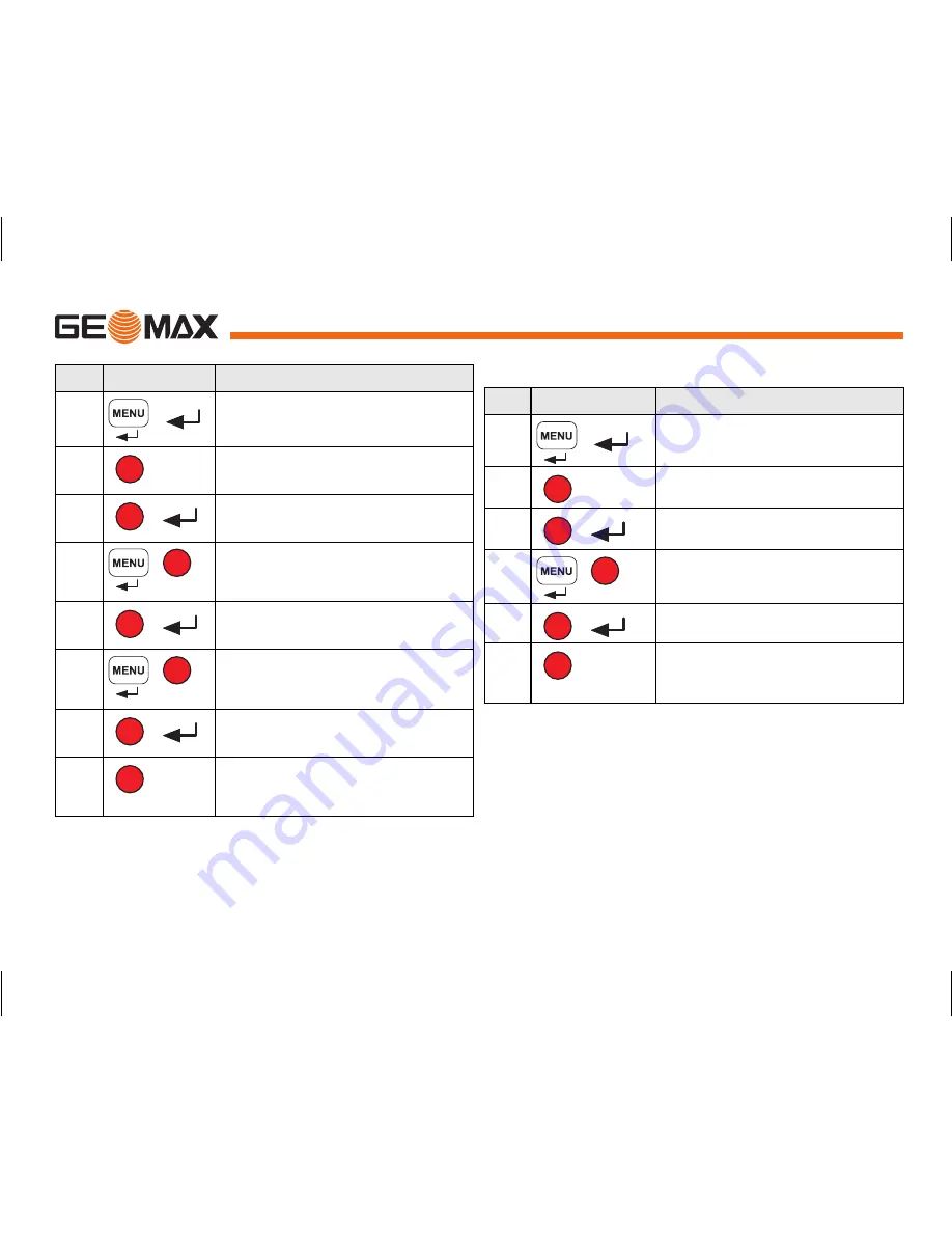
6.4 BF Line Levelling Measurement

Step Key/Screen

Description

1.

Initialize the BIF method.

2.

Initiate measurement to Benchmark.

3.

Backsight measurement displayed.

4.

To start 'Intermediate sight' measure-

ment, go to menu set 'Intermediate Sight' 

to ON or press Height & Distance key.

5.

Intermediate sight measurement 

displayed.

6.

Go to menu set 'Intermediate Sight' to 

OFF or press Height & Distance key, then 

measure to the foresight staff.

7.

Foresight measurement displayed.

8.

System refreshes a standby display for 

measurement to the backsight of next 

change point.

Step Key/Screen

Description

1.

Initialize the BF method

2.

Initiate measurement to Benchmark 

3.

Backsight measurement displayed. 

4.

Measure to the foresight staff.

5.

Foresight measurement displayed.

6.

System refreshes a standby display for 

measurement to the backsight of next 

change point.

Summary of Contents for ZDL700 Series

Page 1: ...User Manual Version 1 0 GeoMax ZDL700...

Page 2: ...nual is valid for ZDL700 Trademarks All trademarks are the property of their respective owners Available documentation Symbols The symbols used in this Manual have the following meanings DANGER Indica...

Page 3: ...nd Transport 20 11 Safety Directions 21 12 Technical Data 27 13 International Limited Warranty Software Licence Agreement 29 14 Index 30 2 Instrument Components Container Contents ZDL700 allen key use...

Page 4: ...er Turn the eyepiece until the cross hairs are sharp or distinct Target Image Focusing Use the gunsight to aim the objective lens at the staff Turn the horizontal fine motion screw until the staff is...

Page 5: ...a On Off Power On or Off switch NONE b MEAS Measuring trigger key Press and hold for 3 seconds to start and stop tracking measure ment timer measurement c Height Distance Alternating between Height an...

Page 6: ...CD backlight illumination ESC key to decline termination of program application or to exit setting in Menu Settings mode Key Symbol 1st level functions 2nd level functions Measurement Mode BF line lev...

Page 7: ...onnected Measurement averaging activated PtID RfID Point ID Reference Benchmark ID Measured staff height BM Benchmark elevation Measured distance dH Height Difference Mean height difference in BFFB El...

Page 8: ...or ASCII format Delete All Data Deleting of all recorded data in the on board internal memory 6 Recording Memory Measurement recorded to on board internal memory In line levelling application recordin...

Page 9: ...t and 0 01 ft for distance In Ft in 1 16 inch Precise Standard ft inch 1 16 inch for height and distance Beep ON OFF Trigger key acoustic signal setting RS232 Baudrate 1200 2400 4800 9600 19200 38400...

Page 10: ...to accept the old entry Clearing all the existing entry field Highlight the first entry field with SPACE character and press ENTER key to clear the entire last input value To discard entry Press ESC k...

Page 11: ...height and distance Step Key Description 1 Press to switch on the instrument GeoMax logo is displayed follow by the default meas urement standby mode 2 Aim at staff and focus Lightly trigger the measu...

Page 12: ...35m 31 11m dH Step Key Screen Description 1 Press key to start height difference and reduced level function 2 A message Meas Reference with input reduced level is displayed 3 Pressmeasuring key to ini...

Page 13: ...to OFF OR press Height Distance key measure to foresight Foresight measurement displayed with prompt message Measure to backsight of next change point with prompt message 1 PtlD 120 000m Elv Meastoba...

Page 14: ...displayed 6 Go to menu set Intermediate Sight to OFFor press Height Distance key then measure to the foresight staff 7 Foresight measurement displayed 8 System refreshes a standby display for measure...

Page 15: ...isplayed 4 Measurement to foresight 5 Foresight measurement displayed 6 Measure to the foresight staff second sighting 7 Foresight second sighting measure ment displayed 8 Measure to the backsight sta...

Page 16: ...ds can hold alpha as well as numeric data Communication Communications parameters of the RS232 interface for data transfer from instrument to computer external device GeoMax standard settings are 1920...

Page 17: ...ar Level 7 3 Optical Collimation Reticle Adjustment If the collimation error exceeds 3 mm over 60 m distance the colli mation needs to be adjusted Step Description 1 Level instrument 2 Turn instrument...

Page 18: ...try input E106 Out Of Level Level the instrument E107 Memory Full Set internal memory to OFF and continue measurement without recording OR download stored data to an external device and continue measu...

Page 19: ...mal position Collimation is out of correction range E117 BM Change Not Allowed Exit to default measurement mode by pressing HEIGHT DISTANCE key and change the Benchmark elevation in the INPUT BM menu...

Page 20: ...Are You Sure Question to prompt user if changing of Reference Benchmark elevation to confirm Wait File System Clean Up Cleaning up of temporary files system files Shut Down System is switching OFF San...

Page 21: ...or freight transport company Field adjustment After transport inspect the field adjustment parameters given in this user manual before using the product 10 2Storage Product Respect the temperature li...

Page 22: ...products with obviously recognizable damages or defects Use with accessories from other manufacturers without the prior explicit approval of GeoMax Inadequate safeguards at the working site for examp...

Page 23: ...se use and can give rise to accidents with far reaching human material financial and envi ronmental consequences Precautions All users must follow the safety directions given by the manufac turer and...

Page 24: ...se in conjunction with GeoMax products CAUTION If the accessories used with the product are not properly secured and the product is subjected to mechanical shock for example blows or falling the produ...

Page 25: ...may enable unau thorized persons to use it in contravention of the regulations exposing themselves and third parties to the risk of severe injury and rendering the environment liable to contamination...

Page 26: ...agnetic radiation may be exceeded and the correct functioning of other products may be impaired Precautions While the product is in use connecting cables for example product to external battery produc...

Page 27: ...Safety Directions ZDL700 26 Labelling...

Page 28: ...ght condition needs longer measuring time in uniform dim light condition 20 lux Circular Bubble Circular Bubble Sensitivity 10 2 mm Compensator Magnet damped pendulum compensator with electronic range...

Page 29: ...cale resolution at 1 upper scale and at 50 gon intervals lower scale Side Drive Movement Play in side drive Continuous horizontal dual drive System MMI capability Measuring applications Keyboard 5 rub...

Page 30: ...ve and is in lieu of all other warranties terms or conditions express or implied either in fact or by operation of law statutory or otherwise including warranties terms or conditions of merchanta bili...

Page 31: ...read and accepted the terms and conditions of the GeoMax Software Licence Agreement Installation or use of the software or any part thereof is deemed to be an acceptance of all the terms and condi ti...

Page 32: ...ob 2 G Gunsight 2 H Height and Distance Measurement 10 Height Difference and Reduced Level Measurement 11 I Icons 6 Input BM 7 Input PtID 7 Intermediate Sight 7 Inverse Staff 7 L Language 8 LCD displa...

Page 33: ...djustment 16 Rounding 8 RS232 8 S Set of Characters 9 Settings 8 Set up Instrument Eyepiece Adjustment 3 Levelling 3 Target Image Focusing 3 Storage 20 Symbols 1 T Tilt Warning 8 Timer 8 Timer Measure...

Page 34: ...GeoMax ZDL700 Series Copyright GeoMax AG Widnau Switzerland 2009 Survey Instrument Sales SurveyInstrumentSales com sales SurveyInstrumentSales com...

Reviews: