10
On some occasions it may be quicker to perform the survey twice, first in one mode and then in
the other.
If minimal effect from any susceptibility variations is desired (for example in archaeological
applications) then the inphase nulling procedure described above must be carried out before
every measurement and the faster way is probably to perform the survey twice, once in each
dipole.
2.5
Equipment Sensitivity Checks
To approximately check the sensitivity of the instrument, with the instrument at 1.5 meters in the
horizontal dipole position set the Mode switch to the 1 m mark and rotate the Q/P zero control
clockwise one turn. Meter should change between 20 and 28 mS/m, for 1 m coil separation and
28 and 30 mS/m for 0.5 m coil separation. Make sure that the zero control is reset to its original
position.
2.6
Automatic Calibration of EM38-MK2
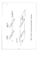
An optional retractable monopod set-up in combination with data logger is provided for an
automatic calibration of EM38-MK2. The set-up provides means of automatic zeroing of the
EM38-MK2. Figure 8 shows the calibration set-up with the instrument in the vertical (VD) and
horizontal (HD) dipole mode, the two geometry used during the automatic calibration of the
instrument. The detailed description of the calibration procedure is described in the EM38-MK2
logger manual.
2.7
Marker Switch
The orange push button switch on the unit front panel can be used during digital data recording
to either initiate recording of a data point in “manual” recording mode or mark a particular
station during the automatic mode recording. More detailed information is provided in the
EM38-MK2 logger manual.
3. SURVEY PROCEDURES
To carry out a survey with the EM38-MK2, one simply lays the instrument on the ground to take
a reading. This can be done either in the vertical dipole mode or in the horizontal dipole mode,
with important differences in the depth response to be described later in this manual.
The EM38-MK2 yields good spatial resolution and measurement stations should be as close as a
meter apart (0.5 m for 0.5 m coil separation) if maximum resolution is to be employed. The
decision as to the correct station spacing will be based on an estimate of the lateral dimensions of
the anticipated conductivity anomalies. Since measurements can be made very quickly it is
better to have too many measurements with good spatial resolution rather than too few.
This instrument is a sensitive detector of small changes in ground conductivity and is responsive
to metal objects either in or on the ground or on the operator. Metal chains around the neck or
wrist, metal wristwatch straps, metal framed glasses, steel supports in boots, coins, keys, or
knives in pockets can be offenders when they are located close to the coils (which are at either
Summary of Contents for EM38-MK2
Page 7: ...5 Fig A...
Page 23: ......
Page 24: ......
Page 25: ......
Page 26: ......
Page 27: ......
Page 28: ......
Page 29: ......
Page 30: ......
Page 31: ......
Page 32: ......
Page 33: ......
Page 34: ......
Page 35: ......
Page 36: ...34...
Page 37: ...35...
Page 38: ...36...
Page 39: ...37...
Page 44: ...42...


