15
which was indicated at the height of 1.5 meters and finally increases to a larger apparent
conductivity.
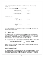
The magnetic susceptibility (in RMKS units) is then given by
K=
57x10
-6
∆σ
a
(mS/m)
(for 1 m)
K=
14.5x10
-6
∆σ
a
(mS/m)
(for 0.5 m)
or in CGS units by
where
a
is the difference in the apparent conductivity measured when the instrument is on the
ground and elevated to 1.5 meters.
7.
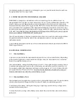
OUTPUT UNITS
The EM38 is calibrated so that under the low induction number approximation the quadrature
component output (Q/P) reads directly in apparent conductivity (
a
). The inphase component
output (I/P) on the EM38-MK2 also reads in units of mS/m; where 28.5 ppt (7.12 for 0.5 m) of
the secondary field relative to the primary field corresponds to 1,000 mS/m.
The following relation can be used to convert mS/m to ppm: 1 mS/m ≡ 28.5 ppm (7.12 for 0.5 m)
where 1 ppm (parts per million) = 1 ppt (parts per thousand)
1000
When the instrument is used with a digital data logger or computer the I/P readings in mS/m are
automatically converted to ppt.
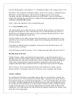
8. CONCLUDING REMARKS
It is hoped that the material given in this manual will assist in survey interpretation. It should be
borne in mind that the strength of the EM38-MK2 lies in the speed and accuracy with which a
reconnaissance conductivity survey can be carried out. While the instrument was not designed
K=
57x10
-6
Δσ
a
(mS/m)
(for 1 m)
4π
K=
14.5x10
-6
Δσ
a
(mS/m)
(for 0.5 m)
4π
Summary of Contents for EM38-MK2
Page 7: ...5 Fig A...
Page 23: ......
Page 24: ......
Page 25: ......
Page 26: ......
Page 27: ......
Page 28: ......
Page 29: ......
Page 30: ......
Page 31: ......
Page 32: ......
Page 33: ......
Page 34: ......
Page 35: ......
Page 36: ...34...
Page 37: ...35...
Page 38: ...36...
Page 39: ...37...
Page 44: ...42...


