5-10
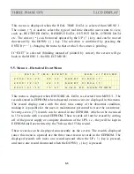
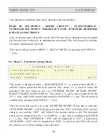
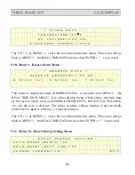
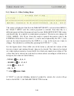
This menu is displayed when the item < BOOST CHARGE > is selected from
MENU 5, the PARAMETER SETTING menu. The user can change the charger
parameters through this menu. The cursor (
→
) can be moved upward by the UP (
↑
)
key, and can be moved downward by the DOWN (
↓
) key. The selection is
confirmed by pressing the ENTER (
←┘
) key. See in the above figure.
<
B O O S T C H A R G E
S E T T I N G
>
→
A U T O - B O O S T ( M O N T H ) = 0 4
0 8
1 2
1 6
2 0 2 4
A U T O - B O O S T ( B A T T L O W ) = 0 4
C H A R G E C U R R E N T = L O
E X I T
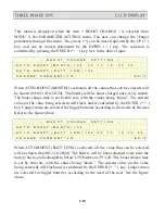
When AUTO-BOOST (MONTH) is selected, all the values that can be selected will
be shown (04/08/12/16/20/24). The battery will be boost charged once every month.
The boost charge time is set by this row, with the values being “hours”. The current
value (or the value being selected) will flash, and is confirmed by the ENTER (
←┘
)
key. Longer times are selected for bigger batteries according to the needs of the user.
Refer to the figure above.
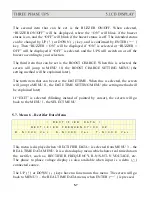
<
B O O S T C H A R G E
S E T T I N G
>
A U T O - B O O S T ( M O N T H ) = 0 4
→
A U T O - B O O S T ( B A T T L O W ) = 0 4
0 8
1 2
1 6 2 0
2 4
C H A R G E C U R R E N T = L O
E X I T
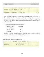
When AUTO-BOOST (BATT LOW) is selected, all the value that can be selected
will be shown (04/08/12/16/20/24). The battery will be boost charged every time the
battery has been discharged to below 12V/battery or 2V/cell. The boost charge time
is set by this row, with the values being “hours”. The current value (or the value
being selected) will flash and is confirmed by the ENTER (
←┘
) key. Longer times
are selected for bigger batteries according to the need of the user. See the figure
above.
Summary of Contents for T3UPS-13-20K
Page 18: ...1 7 Dimension Drawings 10KVA 60KVA OUTLINE DRAWING 1 13...
Page 19: ...10KVA 60KVA INTERIOR DRAWING 1 14...
Page 20: ...75KVA 160KVA OUTLINE DRAWING 1 15...
Page 21: ...75KVA 160KVA INTERIOR DRAWING 1 16...
Page 22: ...175KVA 320KVA OUTLINE DRAWING 1 17...
Page 23: ...175KVA 320KVA INTERIOR DRAWING 1 18...
Page 24: ...INTER PCB DIAGRAM 1 19...
Page 31: ...1...
Page 35: ...3 3...
Page 70: ...ONE TO TWO SERIAL REDUNDANCY 8 3...
Page 77: ...Appendices Additional Data on Options UPSCOMTM UPSCALLTM DCMANTM...
Page 80: ...3...
Page 81: ......

