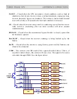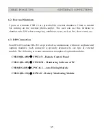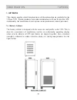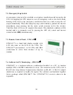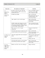
Abnormal
Description & Checkpoint
Solution
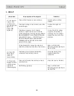
(6) Fans do not
work while
UPS is on.
The fuses positioned behind PCB holder
have been blown or are not installed
properly.
Replace the fuses or install
them properly.
Abnormal voltage output in R phase.
Refer to PCB LED
Detecting Guide and check
the 3T PCB of R phase.
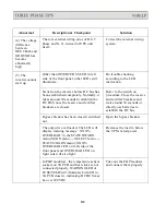
(7) The
rectifier shunt
down and
HIGH DC LED
is lit.
Voltage limit function failure in the 3B,
which contributes to the DC voltage, goes
over 430V.
Refer to PCB LED
Detecting Guide and check
the 3B PCB.
3C PCB has problem.
Refer to PCB LED
Detecting Guide and check
the 3C PCB.
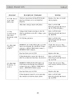
(8) Abnormal
voltage in
reserve.
RESERVE AC FAIL LED lights up. LCD
menu also displays the abnormal voltage
in reserve. (REAL TIME DATA menu
→
RESERVE DATA menu).
Check the reserve wiring
and connect with the correct
source.
Fuse has blown in 3A PCB
Replace the fuse.
If the abnormality cannot be corrected
Refer to PCB LED
after the solution actions have been taken.
Detecting Guide and check
the 3A PCB.
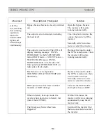
(9) Abnormal
frequency in
reserve.
RESERVE FREQ FAIL LED lights up.
LCD menu also displays the abnormal
voltage in reserve. (REAL TIME DATA
menu
→
RESERVE DATA menu).
Check the reserve wiring
and connect with the correct
source.
Fuse has blown in 3A PCB
Replace the fuse.
If the abnormal cannot be corrected after
Refer to PCB LED
the solution actions have been taken.
Detecting Guide and check
the 3A PCB.
9-3
Summary of Contents for T3UPS-13-20K
Page 18: ...1 7 Dimension Drawings 10KVA 60KVA OUTLINE DRAWING 1 13...
Page 19: ...10KVA 60KVA INTERIOR DRAWING 1 14...
Page 20: ...75KVA 160KVA OUTLINE DRAWING 1 15...
Page 21: ...75KVA 160KVA INTERIOR DRAWING 1 16...
Page 22: ...175KVA 320KVA OUTLINE DRAWING 1 17...
Page 23: ...175KVA 320KVA INTERIOR DRAWING 1 18...
Page 24: ...INTER PCB DIAGRAM 1 19...
Page 31: ...1...
Page 35: ...3 3...
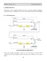
Page 70: ...ONE TO TWO SERIAL REDUNDANCY 8 3...
Page 77: ...Appendices Additional Data on Options UPSCOMTM UPSCALLTM DCMANTM...
Page 80: ...3...
Page 81: ......

