(n) Intelligent battery test:
The batteries are tested after every boost (initiated by
battery discharge or by the monthly boost charge cycle). This is done without
interrupting the operation of the rectifier, preventing the risk of output AC failure
in case of a bad battery. The user is informed of the battery condition, so that
action can be taken before the full capacity of the batteries is needed.
(o) Huge charging power:
The charging power is selectable (Lo/Me/Hi) according
to Ah rating of the batteries, and can charge up battery banks providing more than
8Hrs back-up time without adding an extra charger.
(p) MTBF of fans are extended:
Fans used to cool the UPS, are designed to slow
down under light load, so that the life expectancy of the fans is extended beyond
the normal.
(q) Redundant power supply:
A supplemental power supply is added to provide
redundancy for supplying power to the static switch, so that there will be AC
output no matter what happens to the UPS.
(r) Intelligent interface:
One remote control panel (or one PC) can be used to
monitor up to 99 UPS. The remote control can be used to switch, on or off, any
or all of the UPS systems. When any UPS encounters an emergency condition, the
system will warn the user immediately. All the UPS status, data or commands are
transmitted to external modules through 4 RS-485 ports (for long distance
communication under harsh environment).
(s) Emergency stop is available:
In case of hazard, for example electric shock, fire
or earthquake, the UPS can be shutdown (will have no AC at the output) either
through a switch (can be added upon request) or through smoke detector signal
(can be added upon request) to prevent further injuries or destruction.
1-7
Summary of Contents for T3UPS-33-700K
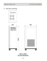
Page 18: ...1 7 Dimension Drawings 10KVA 60KVA OUTLINE DRAWING 1 13 ...
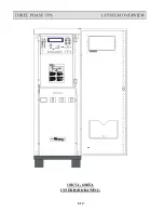
Page 19: ...10KVA 60KVA INTERIOR DRAWING 1 14 ...
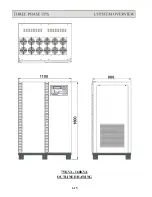
Page 20: ...75KVA 160KVA OUTLINE DRAWING 1 15 ...
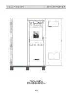
Page 21: ...75KVA 160KVA INTERIOR DRAWING 1 16 ...
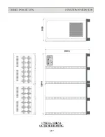
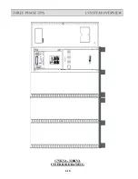
Page 22: ...175KVA 320KVA OUTLINE DRAWING 1 17 ...
Page 23: ...175KVA 320KVA INTERIOR DRAWING 1 18 ...
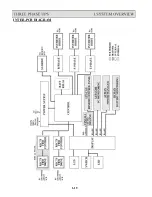
Page 24: ...INTER PCB DIAGRAM 1 19 ...
Page 31: ...1 ...
Page 35: ...3 3 ...
Page 70: ...ONE TO TWO SERIAL REDUNDANCY 8 3 ...
Page 77: ...Appendices Additional Data on Options UPSCOMTM UPSCALLTM DCMANTM ...
Page 80: ...3 ...
Page 81: ......


