5-1
5.
LCD DISPLAY
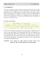
The LCD can display much more information than can the LEDs. In order to make
the display sharp and readable, the LCD is back-lighted by LEDs. But to further
prolong the life of the LEDs, the CPU will cut off power to the LEDs 3 minutes
after the last keystroke of UP, DOWN or ENTER is pressed. The backlighting will
resume if the UP, DOWN or ENTER key is subsequently pressed. Page displays of
the LCD are described below. This screen will refresh once the system power is
enabled (i.e. the default screen).
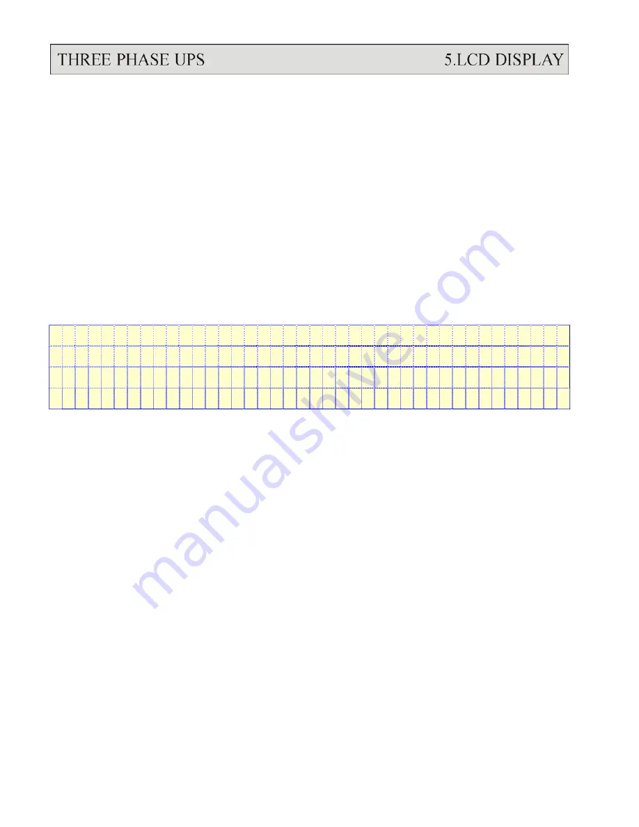
5.1. Menu 0 – Main Menu
W E L C O M E
T O T H E
U P S
M O D E L : 5 0 3 3 A
S
/
N : 1 2 3 4 5 6 7 8 9 0
I D : 0 1
5 0 K V A
I : 2 7 7
/
4 8 0 V
/
6 0 H Z
O : 2 7 7
/
4 8 0 V
/
6 0 H Z
2 0 0 2
/
0 2
/
0 1
T U E
0 8 : 0 0
A M
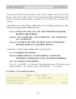
The first row will display the greeting text set by the factory. Changing the text of
this row is not recommended. The model number (MODEL), serial number (S/N),
and the identification number (ID) are displayed in the second row. While the third
row will display the KVA rating, input rating and output rating of the UPS.
Changing the model number of the second row will also change the rating displayed
in the second row (rating is automatically generated by CPU inside the UPS
according to the MODEL number).
WARNING: Never change the model number yourself, because some
parameters will be changed along with the model number.
Summary of Contents for T3UPS-33-700K
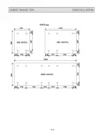
Page 18: ...1 7 Dimension Drawings 10KVA 60KVA OUTLINE DRAWING 1 13 ...
Page 19: ...10KVA 60KVA INTERIOR DRAWING 1 14 ...
Page 20: ...75KVA 160KVA OUTLINE DRAWING 1 15 ...
Page 21: ...75KVA 160KVA INTERIOR DRAWING 1 16 ...
Page 22: ...175KVA 320KVA OUTLINE DRAWING 1 17 ...
Page 23: ...175KVA 320KVA INTERIOR DRAWING 1 18 ...
Page 24: ...INTER PCB DIAGRAM 1 19 ...
Page 31: ...1 ...
Page 35: ...3 3 ...
Page 70: ...ONE TO TWO SERIAL REDUNDANCY 8 3 ...
Page 77: ...Appendices Additional Data on Options UPSCOMTM UPSCALLTM DCMANTM ...
Page 80: ...3 ...
Page 81: ......

