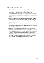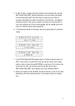
(D) Module Installation
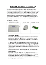
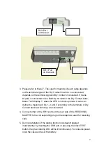
1. Connect either of the RJ11 ports on the rear side of DIALING UNIT to
the corresponding plug on the telephone used for outgoing calls (see
the pictures below).
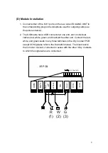
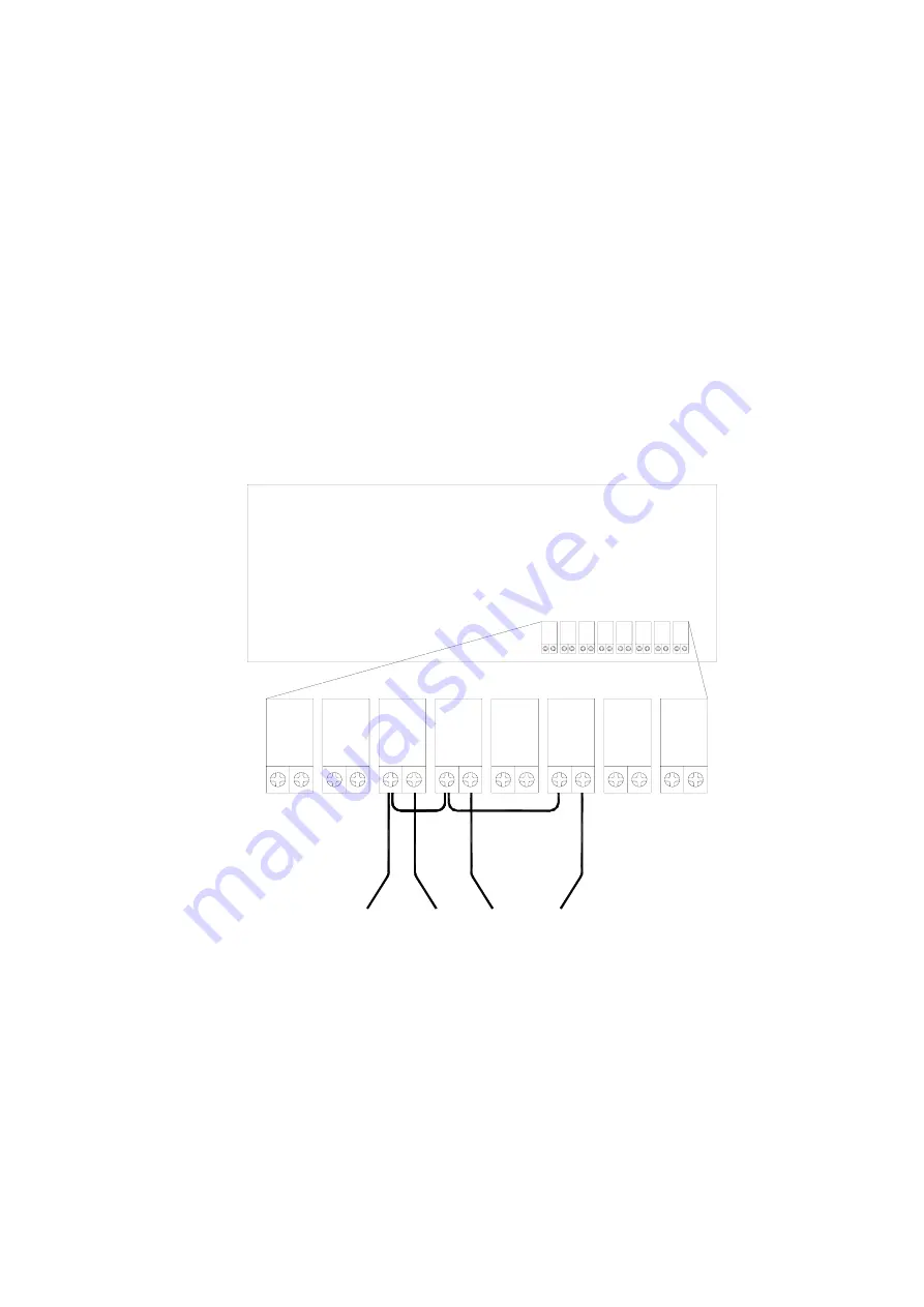
2. The USB cable has a USB connector at one end, and 4 individual
cables (red, white, green, and black)at the other end. Connect the red,
white, and green leads to any three terminals in the Dry Contact PCB
except COM (please refer to the illustration below). The black lead is
the Common Ground, connected in series with the other 3 Dry Contacts
to which the signal wires are connected.
3R PCB
COM
BATL
BACK
-U
P
BY
PA
SS
SS
FA
UL
T
OVL
IN
VO
N
黑
紅
R
(1)
白
W
(2)
綠
G
(3)
乾接點
(DRY CONTACT)
8
Summary of Contents for T3UPS-33-700K
Page 18: ...1 7 Dimension Drawings 10KVA 60KVA OUTLINE DRAWING 1 13 ...
Page 19: ...10KVA 60KVA INTERIOR DRAWING 1 14 ...
Page 20: ...75KVA 160KVA OUTLINE DRAWING 1 15 ...
Page 21: ...75KVA 160KVA INTERIOR DRAWING 1 16 ...
Page 22: ...175KVA 320KVA OUTLINE DRAWING 1 17 ...
Page 23: ...175KVA 320KVA INTERIOR DRAWING 1 18 ...
Page 24: ...INTER PCB DIAGRAM 1 19 ...
Page 31: ...1 ...
Page 35: ...3 3 ...
Page 70: ...ONE TO TWO SERIAL REDUNDANCY 8 3 ...
Page 77: ...Appendices Additional Data on Options UPSCOMTM UPSCALLTM DCMANTM ...
Page 80: ...3 ...
Page 81: ......

