4
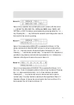
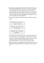
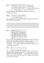
Menu 8
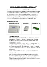
B A T T E R Y
A M O U N T
0 5
Menu 8 is displayed when BATTERY AMOUNT is selected from Menu 6. Here the
used inputs the number of batteries to be monitored (maximum 64). The
↑
or
↓
keys are used to choose the numeric characters. Pressing the
←┘
key confirms
the entry. 2 digits are required in the input, e.g., 35 or 07. The display will return to
Menu 6 by pressing the
←┘
key after the second number is selected.
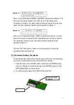
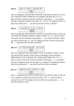
Menu 9
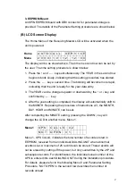
C H A R G E
V O L T A G E
2 2 0
Menu 9 is displayed when CHARGE VLOTAGE is selected from Menu 6. Here the
user enters the charging voltage for a battery charger. The
↑
or
↓
keys are used to
choose the numeric characters. Pressing the
←┘
key confirms the entry. 3 digits
are required in the input, e.g., 230. The display will return to Menu 6 by pressing
the
←┘
key after the third number is selected
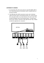
Menu 10
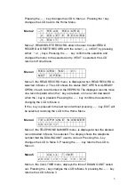
D I S C H A R G E
C Y C L E
3 0
Menu 10 is displayed when DISCHARGE CYCLE is selected from Menu 6. Here
the user inputs the number of days between discharging cycles of batteries.
Battery tests are only conducted under a battery discharging mode. The
↑
or
↓
keys are used to choose the numeric characters. Pressing the
←┘
key confirms
the entry. 2 digits are required in the input, e.g., 30 (days). The display will return to
Menu 6 by pressing the
←┘
key after the second number is selected.
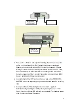
Menu 11
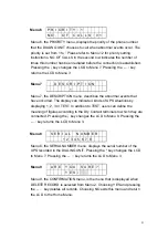
R E P A I R F U N C T I O N
O N
Menu 11 is displayed when REPAIR FUNCTION is selected from Menu 6. Here the
user is allowed to enable the auto-repair function. The
↑
or
↓
keys are used to
choose ‘ON’ or ‘OFF’ The display will return to Menu 6 by pressing the
←┘
key
after the selection is made.
Summary of Contents for T3UPS-33-700K
Page 18: ...1 7 Dimension Drawings 10KVA 60KVA OUTLINE DRAWING 1 13 ...
Page 19: ...10KVA 60KVA INTERIOR DRAWING 1 14 ...
Page 20: ...75KVA 160KVA OUTLINE DRAWING 1 15 ...
Page 21: ...75KVA 160KVA INTERIOR DRAWING 1 16 ...
Page 22: ...175KVA 320KVA OUTLINE DRAWING 1 17 ...
Page 23: ...175KVA 320KVA INTERIOR DRAWING 1 18 ...
Page 24: ...INTER PCB DIAGRAM 1 19 ...
Page 31: ...1 ...
Page 35: ...3 3 ...
Page 70: ...ONE TO TWO SERIAL REDUNDANCY 8 3 ...
Page 77: ...Appendices Additional Data on Options UPSCOMTM UPSCALLTM DCMANTM ...
Page 80: ...3 ...
Page 81: ......

