1.2. Features and Advantages
(a) Reliable input protection:
Circuit breakers are placed in each individual input
loop to ensure power can continue through another loop in case of breaker trip
caused by an abnormal condition in either rectifier or load.
(b) Input surge protection:
An MOV (surge protector) is added at the input,
providing protection to both UPS and the load from any lightning surges, or surges
caused by neighboring large loads.
(c) EMI
suppression:
An EMI filter is added to meet the international EMC limits.
Therefore, very low noise is emitted, and no interference is supplied to other
equipment connected to the same AC source.
(d) Ruggedness:
The rectifier employs phase control technology to regulate the DC
bus voltage. This is the most efficient method to charge the batteries. The SCR
used are inherently rugged. Additionally, a large inductor is added at the input to
avoid deforming the AC source waveform.
(e) High
frequency
design:
The inverter uses high frequency, high efficiency IGBT,
PWM methodology to convert the DC power to AC power. Therefore, the number
of components is fewer, reliability is improved, and the size and weight of UPS is
reduced, performance is improved, and acoustic noise is minimized.
(f) True Galvanic isolation:
An isolation transformer is placed at the output.
This can solve the problem of poor input grounding, can allow a different ground
between input and output, can avoid the annoying problem of ground leakage
current, and can be tied to any potential provided on site. The AC output is
isolated under every mode of operation. Additionally, the user gets the bonus of
attenuation of common mode noise from the output isolation transformer.
1-5
Summary of Contents for Triathlon III T3UPS-11-20K
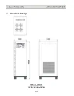
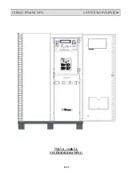
Page 18: ...1 7 Dimension Drawings 10KVA 60KVA OUTLINE DRAWING 1 13 ...
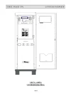
Page 19: ...10KVA 60KVA INTERIOR DRAWING 1 14 ...
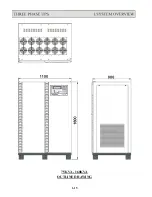
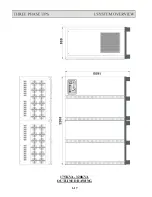
Page 20: ...75KVA 160KVA OUTLINE DRAWING 1 15 ...
Page 21: ...75KVA 160KVA INTERIOR DRAWING 1 16 ...
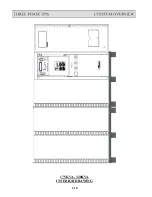
Page 22: ...175KVA 320KVA OUTLINE DRAWING 1 17 ...
Page 23: ...175KVA 320KVA INTERIOR DRAWING 1 18 ...
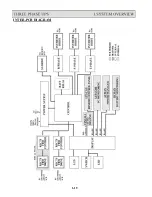
Page 24: ...INTER PCB DIAGRAM 1 19 ...
Page 31: ...1 ...
Page 35: ...3 3 ...
Page 70: ...ONE TO TWO SERIAL REDUNDANCY 8 3 ...
Page 77: ...Appendices Additional Data on Options UPSCOMTM UPSCALLTM DCMANTM ...
Page 80: ...3 ...
Page 81: ......


