5-5
This menu is displayed when the REAL TIME DATA is selected from MENU 1.
The cursor (
→
) is used to select the type of real time data the user wants to view,
such as, RECTIFIER DATA, RESERVE DATA, OUTPUT DATA, OTHER DATA
etc. The cursor (
→
) can be moved upward by the UP (
↑
) key, and can be moved
downward by the DOWN (
↓
) key. The selection is confirmed by pressing the
ENTER (
←┘
), changing the menu to that at which the cursor is pointing.
If “EXIT” is selected (blinking instead of pointed by cursor), the screen will go
back to the MENU 1- the SELECT MENU.
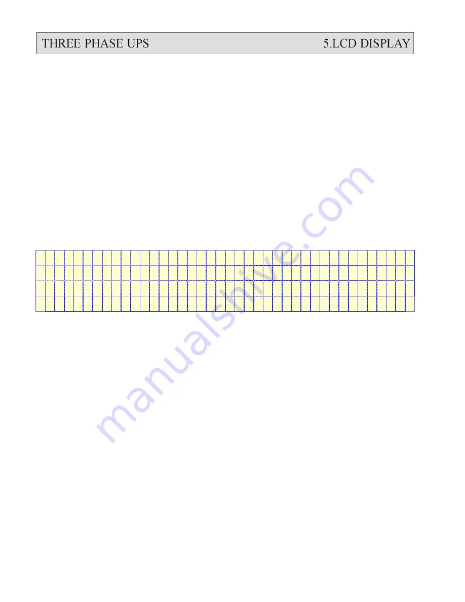
5.5. Menu 4 – Historical Event Menu
<
D A T E
/
T I M E
/
E V E N T S
>
R U N : 2 1 Y R 0 3 M O
2 0 0 0 \ 0 3 \ 2 9
0 9 : 3 2
S H O R T
C I R C U I T
!
2 0 0 0 \ 1 2 \ 0 1
2 2 : 1 5
S H O R T
C I R C U I T
!
2 0 0 1 \ 0 1 \ 1 0
1 5 : 4 7
H I G H D C S H U N T D O W N
This menu is displayed when HISTORICAL DATA is selected from MENU 1. The
records stored in EEPROM when abnormal events occur are displayed in this menu.
The record display starts with the date/ time stamp of the abnormal condition,
making it is possible for the user or maintenance personnel to trace the occurrence.
Seventy-seven (77) records can be stored in one EEPROM, which can be increased
to 154 records with a second EEPROM. These records will not be erased by cutting
off of the power supply or complete shutdown of the UPS, i.e., they will be kept in
EEPROM until overwritten by the 78th (or the 155th) record.
Three records can be displayed concurrently on the screen. The records displayed
(once this menu is opened) are the three most recent records in the EEPROM. The
displayed records will move one record upward when the UP (
↑
) key is pressed,
and move one record downward when the DOWN (
↓
) key is pressed.
Summary of Contents for Triathlon III T3UPS-13-15K
Page 18: ...1 7 Dimension Drawings 10KVA 60KVA OUTLINE DRAWING 1 13...
Page 19: ...10KVA 60KVA INTERIOR DRAWING 1 14...
Page 20: ...75KVA 160KVA OUTLINE DRAWING 1 15...
Page 21: ...75KVA 160KVA INTERIOR DRAWING 1 16...
Page 22: ...175KVA 320KVA OUTLINE DRAWING 1 17...
Page 23: ...175KVA 320KVA INTERIOR DRAWING 1 18...
Page 24: ...INTER PCB DIAGRAM 1 19...
Page 31: ...1...
Page 35: ...3 3...
Page 70: ...ONE TO TWO SERIAL REDUNDANCY 8 3...
Page 77: ...Appendices Additional Data on Options UPSCOMTM UPSCALLTM DCMANTM...
Page 80: ...3...
Page 81: ......


