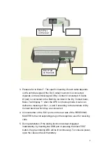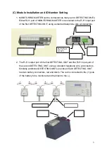
3. Each DETECTING UNIT is given a unique ID number to clearly identify the
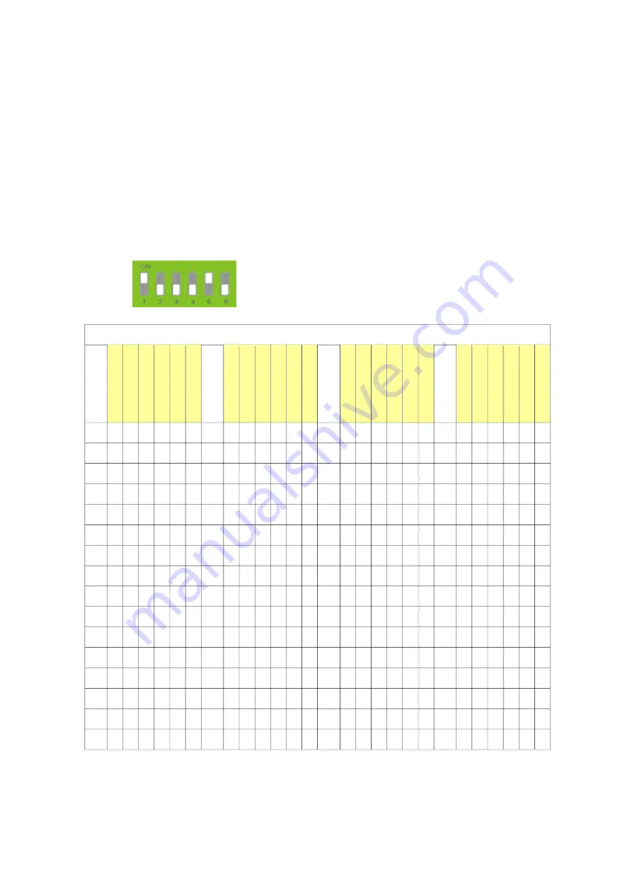
incoming signal. Please refer to the following Binary System Table. The ID
number should be from 1 to 63, converted into binary. The digital ‘0’ is used to
stand for ID number ‘64’. The key position in the 6 key Dip Switch is set
according to the binary digit 0 or 1. 1 is the ON position of the Dip switch. Each
DETECTING UNIT is thus given a unique ID.
4. As an example, if the ID number of a battery is 17, the binary number will be as
100010 (see the table below). Therefore, the first and the fifth key of Dip Switch
should be switched to ‘ON’.
←
6 key Dip Switch
Binary System Table for 6 key Dip Switch
I
D
K
E
Y
1
K
E
Y
2
K
E
Y
3
K
E
Y
4
K
E
Y
5
K
E
Y
6
I
D
K
E
Y
1
K
E
Y
2
K
E
Y
3
K
E
Y
4
K
E
Y
5
K
E
Y
6
I
D
K
E
Y
1
K
E
Y
2
K
E
Y
3
K
E
Y
4
K
E
Y
5
K
E
Y
6
I
D
K
E
Y
1
K
E
Y
2
K
E
Y
3
K
E
Y
4
K
E
Y
5
K
E
Y
6
1 1 0 0 0 0 0 17 1 0 0 0 1 0 33 1 0 0 0 0 1 49 1 0 0 0 0 1
2 0 1 0 0 0 0 18 0 1 0 0 1 0 34 0 1 0 0 0 1 50 0 1 0 0 0 1
3 1 1 0 0 0 0 19 1 1 0 0 1 0 35 1 1 0 0 0 1 51 1 1 0 0 1 1
4 0 0 1 0 0 0 20 0 0 1 0 1 0 36 0 0 1 0 0 1 52 0 0 1 0 1 1
5 1 0 1 0 0 0 21 1 0 1 0 1 0 37 1 0 1 0 0 1 53 1 0 1 0 1 1
6 0 1 1 0 0 0 22 0 1 1 0 1 0 38 0 1 1 0 0 1 54 0 1 1 0 1 1
7 1 1 1 0 0 0 23 1 1 1 0 1 0 39 1 1 1 0 0 1 55 1 1 1 0 1 1
8 0 0 0 1 0 0 24 0 0 0 1 1 0 40 0 0 0 1 0 1 56 0 0 0 1 1 1
9 1 0 0 1 0 0 25 1 0 0 1 1 0 41 1 0 0 1 0 1 57 1 0 0 1 1 1
10 0 1 0 1 0 0 26 0 1 0 1 1 0 42 0 1 0 1 0 1 58 0 1 0 1 1 1
11 1 1 0 1 0 0 27 1 1 0 1 1 0 43 1 1 0 1 0 1 59 1 1 0 1 1 1
12 0 0 1 1 0 0 28 0 0 1 1 1 0 44 0 0 1 1 0 1 60 0 0 1 1 1 1
13 1 0 1 1 0 0 29 1 0 1 1 1 0 45 1 0 1 1 0 1 61 1 0 1 1 1 1
14 0 1 1 1 0 0 30 0 1 1 1 1 0 46 0 1 1 1 0 1 62 0 1 1 1 1 1
15 1 1 1 1 0 0 31 1 1 1 1 1 0 47 1 1 1 1 0 1 63 1 1 1 1 1 1
16 0 0 0 0 1 0 32 0 0 0 0 0 1 48 0 0 0 0 1 1 64 0 0 0 0 0 0
6
Summary of Contents for Triathlon III T3UPS-13-15K
Page 18: ...1 7 Dimension Drawings 10KVA 60KVA OUTLINE DRAWING 1 13...
Page 19: ...10KVA 60KVA INTERIOR DRAWING 1 14...
Page 20: ...75KVA 160KVA OUTLINE DRAWING 1 15...
Page 21: ...75KVA 160KVA INTERIOR DRAWING 1 16...
Page 22: ...175KVA 320KVA OUTLINE DRAWING 1 17...
Page 23: ...175KVA 320KVA INTERIOR DRAWING 1 18...
Page 24: ...INTER PCB DIAGRAM 1 19...
Page 31: ...1...
Page 35: ...3 3...
Page 70: ...ONE TO TWO SERIAL REDUNDANCY 8 3...
Page 77: ...Appendices Additional Data on Options UPSCOMTM UPSCALLTM DCMANTM...
Page 80: ...3...
Page 81: ......

