
11
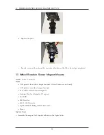
WHEEL ROTATION SENSOR MAGNET MOUNTS
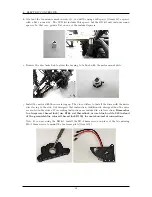
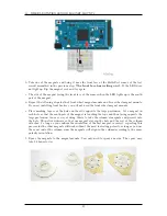
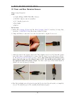
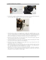
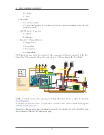
b. Take one of the magnets and bring it near the front face of the Hall-effect sensor of the test
circuit assembled in the previous step.
The front face has writing on it.
If the LED does
not light up, flip the magnet over and try again.
c. The side of the magnet facing the front face of the sensor when the LED lights up is the south
pole of the magnet.
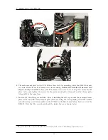
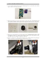
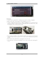
d. Repeat the following steps for the 2 front wheel magnet mounts and 2 rear wheel magnet mounts.
If you are installing front brakes, you will not need the front wheel magnet mounts.
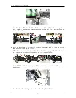
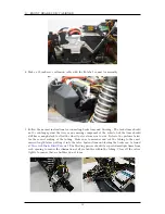
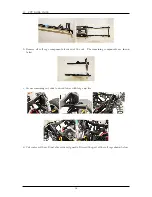
e. Place masking tape over the holes on the side opposite the large protrusion. Set a magnet in
each hole so that the south pole of the magnet is touching the tape and thus facing opposite the
large protrusion. An easy way of doing this is to take the column of magnets and press it into
the hole. Then slide sideways so that one magnet stays in the hole and the rest of the column
detaches. So long as you confirm the orientation of the first magnet is correct, repeating this
process for the other magnets will work without the need for testing polarity so long as you use
the same end of the column, since the magnets will align in the column according to the same
polarity orientation.
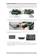
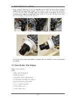
f. Epoxy the magnets to the magnet mounts. You only need to epoxy one side. The epoxy may
take 24 hours to dry.
25
Summary of Contents for AutoRally
Page 1: ...AutoRally Chassis Instructions Version 1 4 June 2018 Georgia Institute of Technology...
Page 2: ......
Page 79: ...27 APPENDIX A PARTS Futaba FUTM1725 Charger for Futaba 4PV Glitch Capacitor GPS antenna 75...
Page 80: ...27 APPENDIX A PARTS GPS antenna cable GPS box fan Hallogic OH090U Hall Effect sensors 76...
Page 88: ...27 APPENDIX A PARTS 1 M3 4mm screw 27 7 3 GPS Box 8 M3 8mm screws 4 M3 hex nuts 84...
Page 89: ...27 APPENDIX A PARTS 2 M1 4 fan screws 2 M1 4 fan nuts 2 M3 25mm screws 85...
Page 92: ......