

19
PROTOSHIELD ASSEMBLY
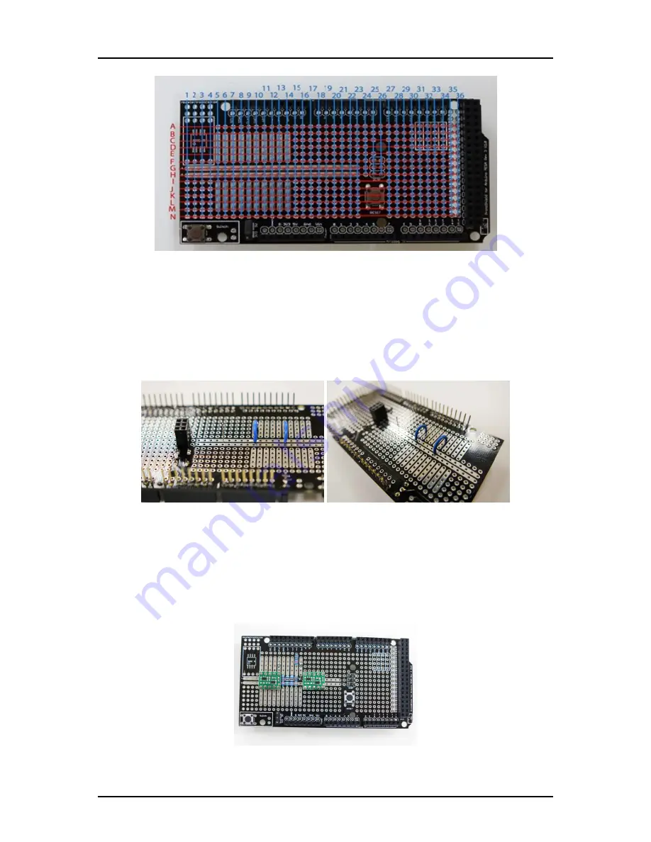
Instructions
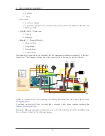
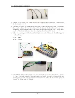
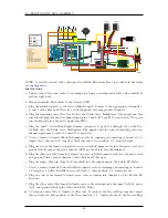
a. Assemble the base protoshield kit, including its various headers, buttons, and jumpers.
b. Make sure the voltage selection jumper on the ProtoShield is set to 3.3V.
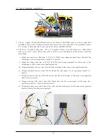
c. Cut two 1” lengths of blue wire and one 1/4” length of uninsulated wire (or scrap leads cut from
capacitors or resistors). Solder one blue wire to connect pads D9 to G9 and D14 to G14. Solder
the uninsulated wire to connect pads F19 to G19.
d. Place and solder 2 level shifters. Pin 1 of the first level shifter (octagonal pad next to the exposed
circular pad) should be placed in pad I9. Pin 1 of the second level shifter should be placed in
pad I19.
e. Place and solder three 10kΩ resistors connecting F10 F12 to I10 - I12.
f. Place and solder a 3.3kΩ resistor connecting F13 to I13. Solder a 2.2kΩ resistor connecting D13
to A13.
39
Summary of Contents for AutoRally
Page 1: ...AutoRally Chassis Instructions Version 1 4 June 2018 Georgia Institute of Technology...
Page 2: ......
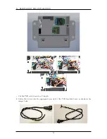
Page 79: ...27 APPENDIX A PARTS Futaba FUTM1725 Charger for Futaba 4PV Glitch Capacitor GPS antenna 75...
Page 80: ...27 APPENDIX A PARTS GPS antenna cable GPS box fan Hallogic OH090U Hall Effect sensors 76...
Page 88: ...27 APPENDIX A PARTS 1 M3 4mm screw 27 7 3 GPS Box 8 M3 8mm screws 4 M3 hex nuts 84...
Page 89: ...27 APPENDIX A PARTS 2 M1 4 fan screws 2 M1 4 fan nuts 2 M3 25mm screws 85...
Page 92: ......