

20
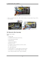
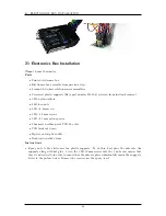
ELECTRONICS BOX ASSEMBLY
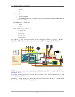
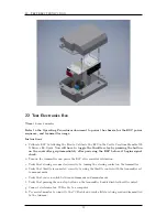
NOTE: A scalable version of the drawings (AutoRally Electronics Box) is available in the folder
Instructions
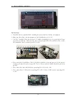
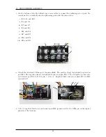
a. Upload code to Due and verify it is sending data using a serial monitor (data values should be
garbage right now).
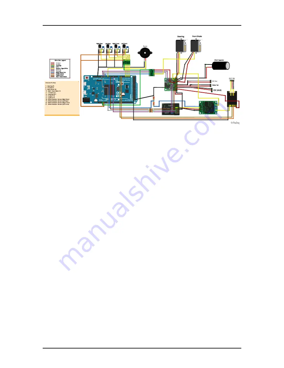
b. Mount assembled Protoshield to the Arduino DUE.
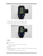
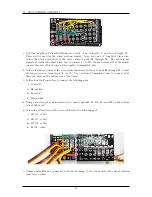
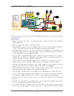
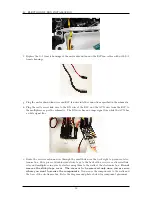
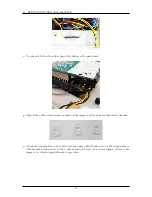
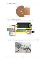
c. Plug the middle connector of the Green-Blue-Purple Y-harness to the signal pins of channels 1,
2, and 3 of the Futaba RC Receiver, with the purple wire plugged into channel 1.
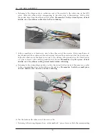
d. Plug the remaining end of the Y-cable into the Pololu Servo Multiplexer. The purple and blue
wires should plug into master channel signal pins 1 and 2 (M1 and M2), respectively. The green
wire should plug into the select signal pin (SEL).
e. Plug the non-Y, Green-Blue-Purple harness, connected to pads J16 through J18 on the Pro-
toShield, into the Pololu Servo Multiplexer. The purple and blue wires should plug into slave
channel signal pins 1 and 2 (S1 and S2), respectively.
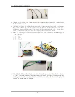
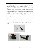
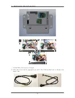
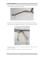
f. Create a female-to-female Black-Red jumper cable by crimping and inserting each end of a 6”
length of red wire and a 6” length of black wire into a two-position, 0.1” female header.
g. Plug one end of the female-to-female two-wire, red-black jumper cable into the power (red) and
ground (black) pins of the select channel (SEL) on the Pololu Servo Multiplexer.
h. Plug the other end of the female-to-female two-wire, red-black jumper cable into the power (red)
and ground (black) pins of channel 3 of the Futaba RC Receiver.
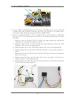
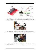
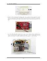
i. Plug the single, blue wire from the Protoshield into the output pin on the Pololu RC Relay.
j. Create a female-to-female Yellow-Red-Black jumper cable by crimping and inserting each end of
a 6”length of a Yellow-Red-Black servo cable into a three-position, 0.1” female header.
k. Plug one end of the female-to-female servo cable extension into channel 4 of the Futaba RC
Receiver.
l. Plug the other end of the female-to-female servo cable extension into the input (yellow), power
(red), and ground (black) pins of the Pololu RC Relay.
m. l. Crimp one end of the 6” length of yellow wire. If you have the Racers Edge capacitor, insert
this end into the first-position of the three-position, 0.1” female header on the Racers Edge
46
Summary of Contents for AutoRally
Page 1: ...AutoRally Chassis Instructions Version 1 4 June 2018 Georgia Institute of Technology...
Page 2: ......
Page 79: ...27 APPENDIX A PARTS Futaba FUTM1725 Charger for Futaba 4PV Glitch Capacitor GPS antenna 75...
Page 80: ...27 APPENDIX A PARTS GPS antenna cable GPS box fan Hallogic OH090U Hall Effect sensors 76...
Page 88: ...27 APPENDIX A PARTS 1 M3 4mm screw 27 7 3 GPS Box 8 M3 8mm screws 4 M3 hex nuts 84...
Page 89: ...27 APPENDIX A PARTS 2 M1 4 fan screws 2 M1 4 fan nuts 2 M3 25mm screws 85...
Page 92: ......