

21
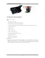
ELECTRONICS BOX INSTALLATION
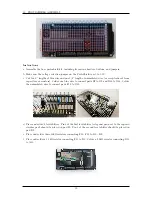
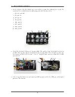
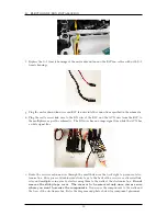
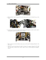
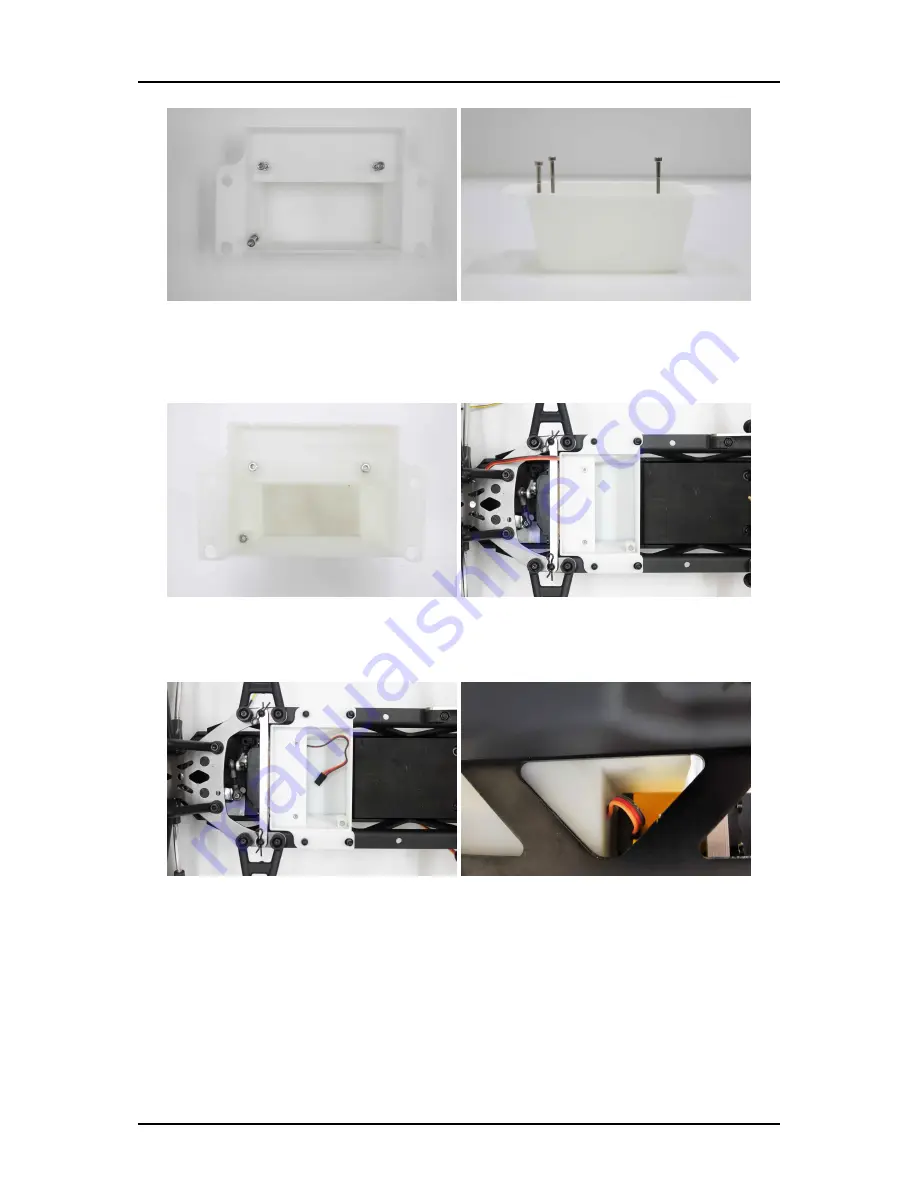
b. Install the M3
×
6 mm screw and an M3 nut in the hole at the bottom of the electronics box with
the head of the screw on the bottom of the electronics box. Place electronics box assembly in
chassis with the mounting holes pressed over the plastic supports on the chassis.
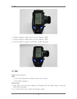
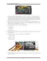
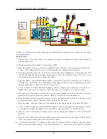
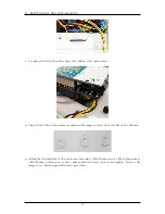
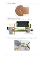
c. Route the steering servo cable into the electronics box through the steering servo cable hole on
the front of the box (near the base of the box).
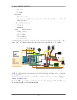
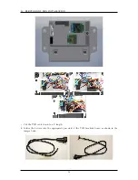
d. Plug the steering servo cable into the appropriate pins on the servo multiplexer per the diagram.
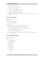
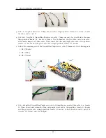
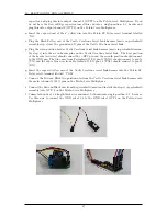
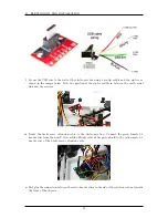
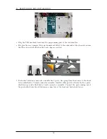
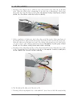
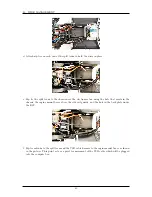
e. Bring the components put together in the previous section near the box to install them inside.
Route only the front rotation sensor harnesses through the slot in the box as shown in the picture
below. The rear rotation sensor harnesses should go out the back where they will eventually go
through the split loom.
49
Summary of Contents for AutoRally
Page 1: ...AutoRally Chassis Instructions Version 1 4 June 2018 Georgia Institute of Technology...
Page 2: ......
Page 79: ...27 APPENDIX A PARTS Futaba FUTM1725 Charger for Futaba 4PV Glitch Capacitor GPS antenna 75...
Page 80: ...27 APPENDIX A PARTS GPS antenna cable GPS box fan Hallogic OH090U Hall Effect sensors 76...
Page 88: ...27 APPENDIX A PARTS 1 M3 4mm screw 27 7 3 GPS Box 8 M3 8mm screws 4 M3 hex nuts 84...
Page 89: ...27 APPENDIX A PARTS 2 M1 4 fan screws 2 M1 4 fan nuts 2 M3 25mm screws 85...
Page 92: ......


